
Quantitative pneumatic otoscopy using coherent light ranging techniques

a light ranging and quantitative technology, applied in the field of three-dimensional imaging of ear tissue, can solve the problems of limited clinical practice, limited use experience, and limited scope of primary care or general pediatrician's office limitations

Active Publication Date: 2018-01-16
THE BOARD OF TRUSTEES OF THE UNIV OF ILLINOIS
View PDF14 Cites 21 Cited by
  • Summary
  • Abstract
  • Description
  • Claims
  • Application Information

AI Technical Summary

Benefits of technology

The present invention provides a system for pneumatic otoscopic imaging that can characterize ear tissue under different pressure conditions. The system includes a hand-held otoscope with a light source and a pneumatic port for controlling pressure in the ear canal. The system can also have an interferometer for combining scattered light from the ear tissue with a reference beam and a controller for modulating pressure in the ear canal. The system can also have a camera for imaging scattering from the surface of the ear canal and the tympanic membrane, and a pump for generating pressure in the ear canal. The invention also provides methods for characterizing biofilm and effusions in the middle ear of a person using pneumatic otoscopy. The technical effects of the invention include improved imaging of ear tissue and the ability to diagnose and treat ear pathologies.

Problems solved by technology

One of the biggest problems with current pneumatic otoscopes is that they require a lot of user experience to be effective.
Currently, few objective tests are available to assess the significance of disease, and limitations are more evident in the primary care or general pediatrician's office, remote from access to specialists in otolaryngology.
Furthermore, evaluation and monitoring of treatments (such as antibiotic treatments in OM or OME) in patients is often difficult, because quantitative measures are lacking.
All these limitations can be ultimately attributed to the qualitative nature of the information acquired, and flow from the fact that a prior art pneumatic otoscope is basically a low-magnification microscopy-type of instrument.
A divergent beam will deteriorate the collection efficiency of the back-reflected optical signal.

Method used


Image

  • Quantitative pneumatic otoscopy using coherent light ranging techniques
  • Quantitative pneumatic otoscopy using coherent light ranging techniques
  • Quantitative pneumatic otoscopy using coherent light ranging techniques

Examples


Embodiment Construction

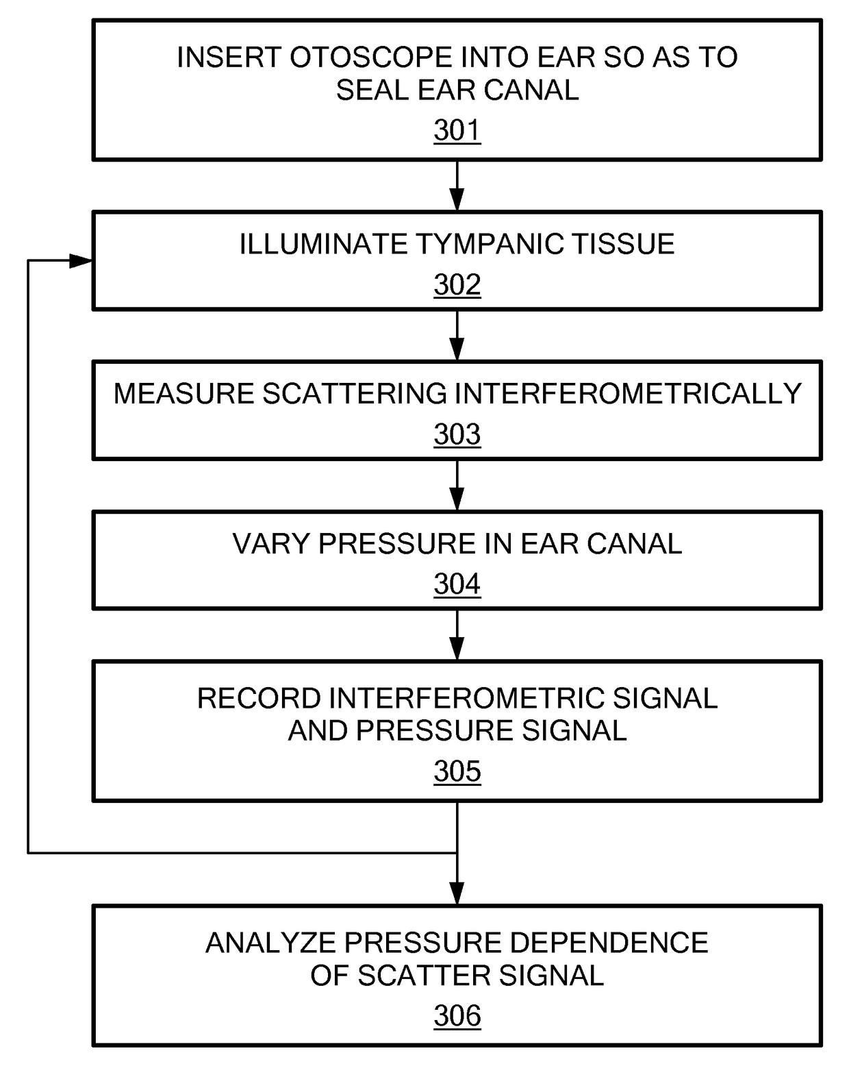
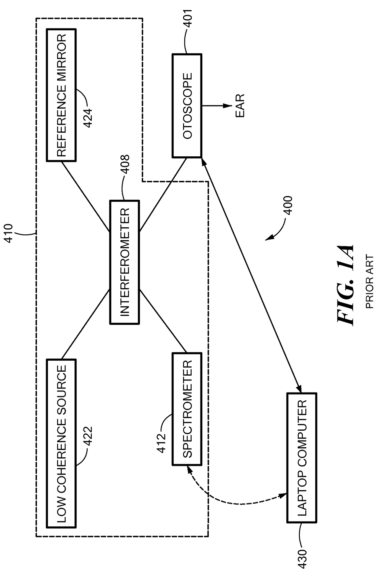
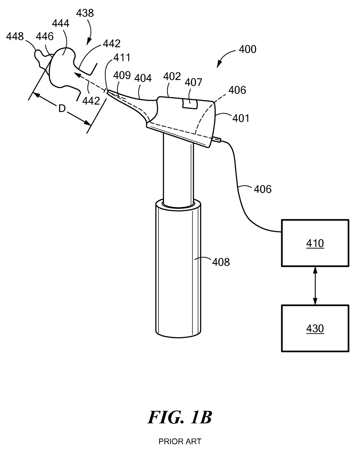
[0029]In accordance with embodiments of the invention, a system is provided for pneumatic otoscopic imaging. The system has a source of light and a hand-held otoscope for abutment with an ear canal for directing the light to ear tissue and for collecting scattered light from the ear tissue. The system also has an interferometer for combining the scattered light from the ear tissue with a reference beam for generating an interferometry signal, a pneumatic port coupled to the hand-held otoscope for governing a pressure within the ear canal, a pump for varying the pressure within the ear canal and for generating a pressure signal, and a processor for receiving the interferometry signal and the pressure signal and for generating therefrom a quantitative characterization of the ear tissue under a specified condition of pressure within the ear canal.

[0030]In accordance with alternate embodiments of the present invention, the pneumatic otoscopic imaging system may also have a controller fo...


PUM


Abstract

Methods and apparatus for performing interferometric measurements on ear tissue within a person's ear, wherein the measurements are performed as a function of pressure within the ear canal. Measurements may be performed at a plurality of pressures, including pressures greater than, and less than, atmospheric pressure. Using an apparatus in accordance with the invention, methods are provided for characterizing a tympanic membrane, as well as a biofilm adjacent to the tympanic membrane, and an effusion in the middle ear. The tympanic membrane may be characterized as to geometrical features and mobility. Characterizations provided by the apparatus serve to diagnose ear pathology.

Description

[0001]The present application claims priority of U.S. Provisional Patent Application Ser. No. 61 / 869,805, filed Aug. 26, 2013, and incorporated herein by reference.[0002]This invention was made with government support under Grant R01 EB013723, awarded by the National Institutes of Health. The Government has certain rights in the invention.TECHNICAL FIELD[0003]The present invention relates to apparatus and methods for imaging otoscopy, and, more particularly, to apparatus and methods for three-dimensional imaging of ear tissue under conditions of controlled pressure in the ear canal.BACKGROUND ART[0004]Low-coherence interferometry (LCI) is a well-known optical coherence technique capable of measuring one-dimensional depth-resolved tissue structure with a typical resolution of several microns. Optical Coherence Tomography (OCT) combines LCI with a lateral scanning mechanism to generate cross-sectional images of biological tissues. LCI and OCT are non-invasive imaging techniques, typic...

Claims


Application Information

Patent Timeline
IPC IPC(8): A61B6/00A61B5/00A61B1/227
CPCA61B1/2275A61B5/0075A61B5/0053
Inventor BOPPART, STEPHEN A.SHELTON, RYAN
Owner THE BOARD OF TRUSTEES OF THE UNIV OF ILLINOIS
Learn More