Polarization-maintaining optical fiber and bidirectional optical transmission apparatus

Inactive Publication Date: 2018-01-23
THE FUJIKURA CABLE WORKS LTD
View PDF10 Cites 0 Cited by
  • Summary
  • Abstract
  • Description
  • Claims
  • Application Information

AI Technical Summary

Benefits of technology

The patent text explains that using two transmission and receiving units with different types to create a pair of optical devices increases manufacturing costs and decreases maintenance. So, the technical effect of the patent is to provide a way to reduce costs and improve maintenance of optical devices.

Problems solved by technology

In this manner, using two transmission and receiving units having different types which form a pair leads to an increase in cost during the manufacturing of a bidirectional optical transmission apparatus or a decrease in its maintenance.

Method used


Image

  • Polarization-maintaining optical fiber and bidirectional optical transmission apparatus
  • Polarization-maintaining optical fiber and bidirectional optical transmission apparatus
  • Polarization-maintaining optical fiber and bidirectional optical transmission apparatus

Examples


first embodiment

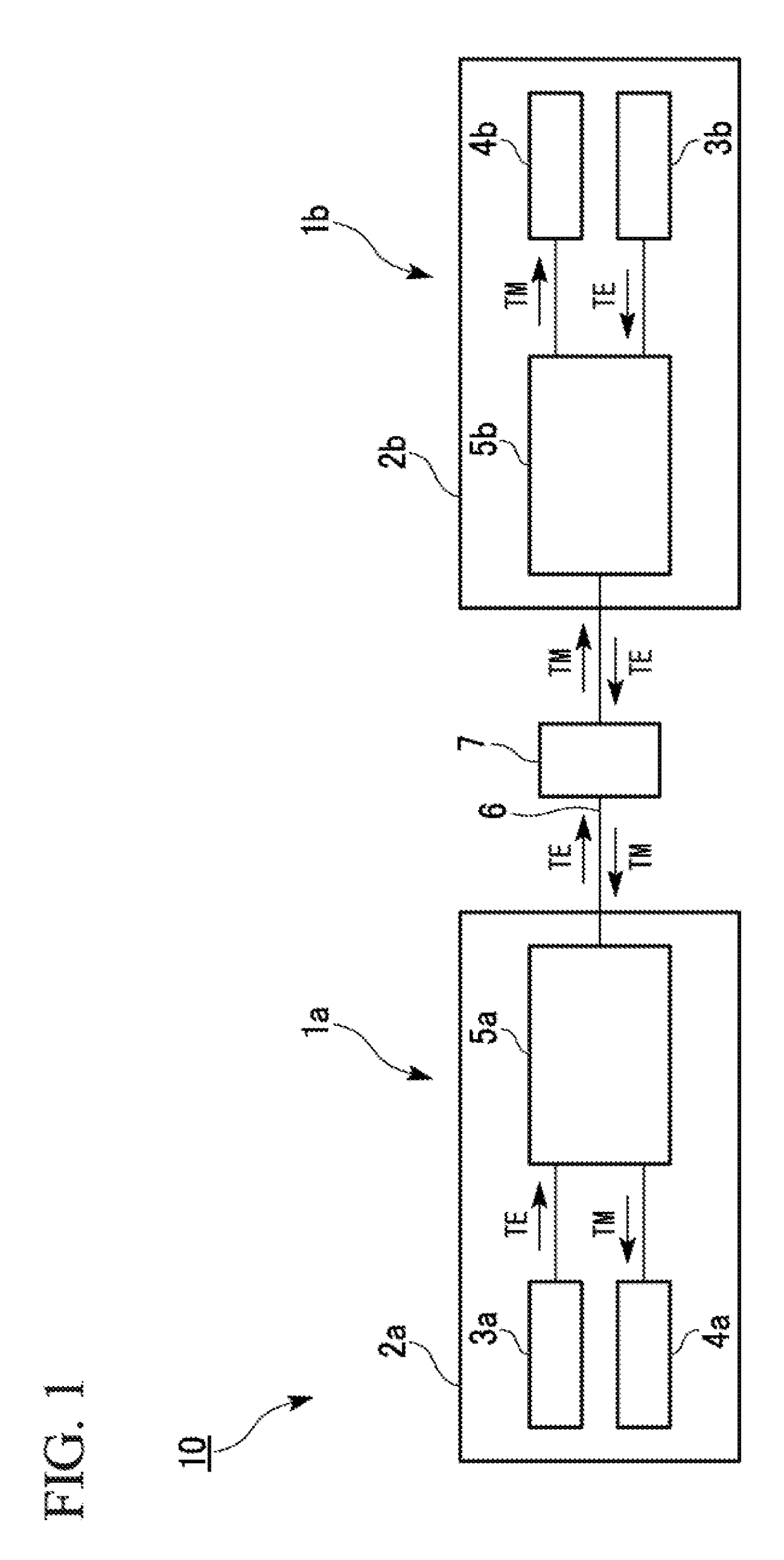
[0022]The configuration of a bidirectional optical transmission apparatus according to a first embodiment will be described below with reference to FIG. 1.

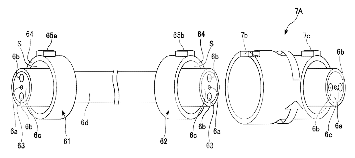
[0023]As shown in FIG. 1, a bidirectional optical transmission apparatus 10 includes an optical waveguide device (first optical waveguide device) 1a, an optical waveguide device (second optical waveguide device) 1b, and a polarization-maintaining optical fiber 6.

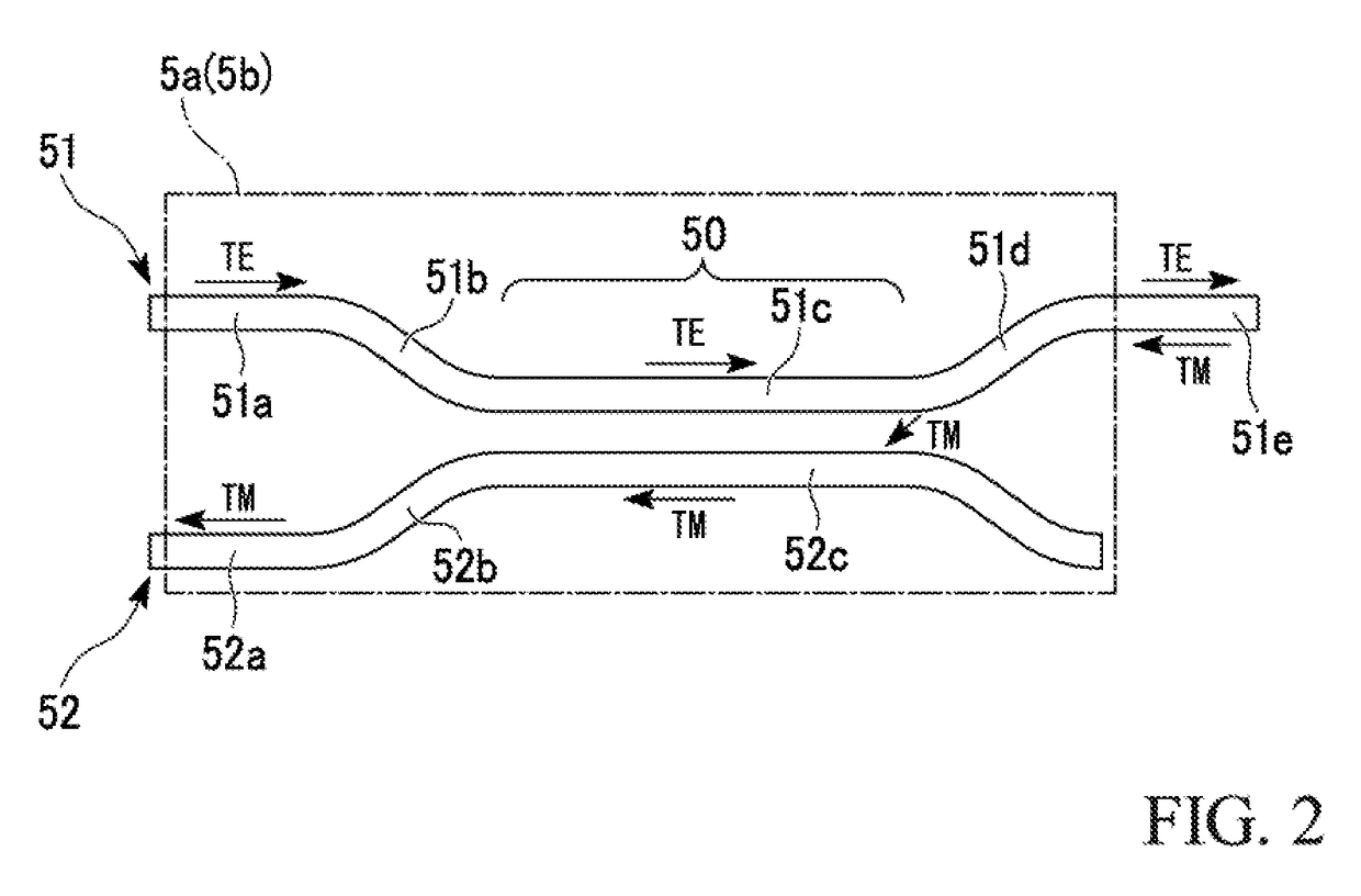
[0024]In addition, as shown in FIG. 1, the optical waveguide device (planar optical waveguide device) 1a includes a substrate (first substrate) 2a, an optical transmission unit (first optical transmission unit) 3a, an optical receiving unit (first optical receiving unit) 4a, and a polarization coupler / splitter unit (first polarization coupler / splitter unit) 5a. The optical waveguide device (planer optical waveguide device) 1b includes a substrate (second substrate) 2b, an optical transmission unit (second optical transmission unit) 3b, an optical receiving unit (second opt...

second embodiment

[0078]Next, a second embodiment will be described, but the basic configuration thereof is the same as that of the first embodiment. Therefore, the same components are denoted by the same reference numerals and signs, and a description thereof will not be given. Only points which are different therefrom will be described.

[0079]The present embodiment is different from the first embodiment, in that optical waveguide devices 1a and 1b include a plurality of transmission and receiving units.

[0080]As shown in FIG. 5, a bidirectional optical transmission apparatus 20 of the present embodiment includes the optical waveguide devices 1a and 1b, a plurality of polarization-maintaining optical fibers 6, and a polarization rotation unit 7.

[0081]The optical waveguide device 1a includes a substrate 2a and a plurality of transmission and receiving units (first transmission and receiving units) 8a to 8c disposed on the substrate 2a. Each of the transmission and receiving units 8a to 8c includes an o...

third embodiment

[0091]Next, a third embodiment will be described, but the basic configuration thereof is the same as that of the first embodiment. Therefore, the same components are denoted by the same reference numerals and signs, and a description thereof will not be given. Only points which are different therefrom will be described.

[0092]A bidirectional optical transmission apparatus 30 of the present embodiment is different from that of the first embodiment, in that optical waveguide devices 1a and 1b include polarization rotators 9a and 9b, respectively, as shown in FIG. 7.

[0093]The polarization rotators 9a and 9b change the direction of the electric field plane of a light wave. An example of the polarization rotators 9a and 9b capable of being used includes a polarization conversion element having a structure with a two-step height with respect to a silicon waveguide, as disclosed in PCT International Publication No. WO 2014 / 207949. As shown in FIG. 7, the polarization rotator 9a is connected...


PUM


Abstract

A bidirectional optical transmission apparatus includes a first optical waveguide device, a second optical waveguide device, and a polarization-maintaining optical fiber that connects the first optical waveguide device and the second optical waveguide device. A direction of a slow axis of the polarization-maintaining optical fiber with respect to a first substrate at a connecting portion between the first optical waveguide device and the polarization-maintaining optical fiber and a direction of the slow axis of the polarization-maintaining optical fiber with respect to the second substrate at a connecting portion between the second optical waveguide device and the polarization-maintaining optical fiber are substantially orthogonal to each other.

Description

BACKGROUND OF THE INVENTIONField of the Invention[0001]The present invention relates to a polarization-maintaining optical fiber and a bidirectional optical transmission apparatus.[0002]Priority is claimed on Japanese Patent Application No. 2016-223444, filed on Nov. 16, 2016, the content of which is incorporated herein by reference.Description of Related Art[0003]Hitherto, a bidirectional optical transmission apparatus as disclosed in Japanese Unexamined Patent Application, First Publication No. S62-3205 has been known. This bidirectional optical transmission apparatus includes a first transmission and receiving unit, a second transmission and receiving unit, and a polarization-maintaining optical fiber. The first transmission and receiving unit includes a first optical transmission unit, a first optical receiving unit, and a first polarization coupler / splitter unit. The first polarization coupler / splitter unit is connected to the first optical transmission unit and the first optic...

Claims


Application Information

Patent Timeline
IPC IPC(8): G02B6/00G02F1/01G02B6/42G02B6/27
CPCG02B6/2793G02B6/2726G02B6/2773G02B6/4213G02B6/4216G02B6/2766G02B6/2733G02F1/0134G02B6/4246G02B6/126H04B10/2589
Inventor GOI, KAZUHIRO
Owner THE FUJIKURA CABLE WORKS LTD
Why Eureka
Try Eureka