Audio signal noise attenuation

a technology of audio signal and noise attenuation, applied in the field of noise attenuation, can solve the problems of reducing the noise of single-microphones in mobile telephony, unable to use beam formers to suppress high noise levels, and the absence of multiple microphones, so as to facilitate noise attenuation and reduce computational resources , the effect of efficient noise attenuation

Active Publication Date: 2018-01-23
KONINK PHILIPS ELECTRONICS NV
View PDF24 Cites 1 Cited by
  • Summary
  • Abstract
  • Description
  • Claims
  • Application Information

AI Technical Summary

Benefits of technology

[0010]The invention may provide improved and / or facilitated noise attenuation. In many embodiments, a substantially reduced computational resource is required. The approach may allow more efficient noise attenuation in many embodiments which may result in faster noise attenuation. In many scenarios the approach may enable or allow real time noise attenuation.
[0041]This may provide a particularly efficient implementation and may in particular reduce complexity.

Problems solved by technology

A particularly challenging application is single-microphone noise reduction in mobile telephony.
On the other hand, the absence of multiple microphones precludes beam former-based solutions to suppress the high levels of noise that may be present.
Spatial filtering techniques such as beam-forming can only achieve limited success in such scenarios and additional noise suppression needs to be performed on the output of the beam-former in a post-processing step.
The use of noise codebooks in a practical implementation however is challenging due to the variety of noise types that may be encountered in practice.
As a result a very large noise codebook is typically used.
This results in computationally very resource demanding process that is often not practical for especially low complexity devices.
Furthermore, the large noise codebooks are cumbersome to generate and store, and the large number of possible noise candidates may increase the risk of an erroneous estimate resulting in a suboptimal noise attenuation.

Method used


Image

  • Audio signal noise attenuation
  • Audio signal noise attenuation
  • Audio signal noise attenuation

Examples


Embodiment Construction

[0051]The following description focuses on embodiments of the invention applicable to speech enhancement by attenuation of noise. However, it will be appreciated that the invention is not limited to this application but may be applied to many other signals.

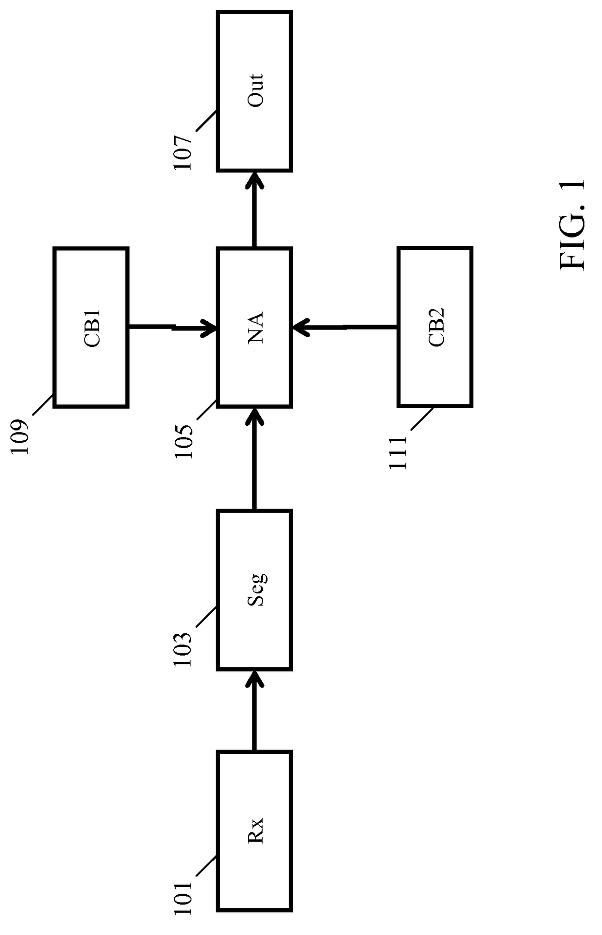
[0052]FIG. 1 illustrates an example of a noise attenuator in accordance with some embodiments of the invention.

[0053]The noise attenuator comprises a receiver 101 which receives a signal that comprises both a desired component and an undesired component. The undesired component is referred to as a noise signal and may include any signal component not being part of the desired signal component.

[0054]In the system of FIG. 1, the signal is an audio signal which specifically may be generated from a microphone signal capturing an audio signal in a given audio environment. The following description will focus on embodiments wherein the desired signal component is a speech signal from a desired speaker. The noise signal component may inc...


PUM


Abstract

A noise attenuation apparatus receives an audio signal comprising a desired and a noise signal component. Two codebooks (109, 111) comprise respectively desired signal candidates representing a possible desired signal component and noise signal contribution candidates representing possible noise contributions. A segmenter (103) segments the audio signal into time segments and for each time segment a noise attenuator (105) generates estimated signal candidates by for each of the desired signal candidates generating an estimated signal candidate as a combination of a scaled version of the desired signal candidate and a weighted combination of the noise signal contribution candidates. The noise attenuator (105) minimizes a cost function indicative of a difference between the estimated signal candidate and the audio signal in the time segment. A signal candidate is then determined for the time segment from the estimated signal candidates and the audio signal is noise compensated based on this signal candidate.

Description

FIELD OF THE INVENTION[0001]The invention relates to audio signal noise attenuation and in particular, but not exclusively, to noise attenuation for speech signals.BACKGROUND OF THE INVENTION[0002]Attenuation of noise in audio signals is desirable in many applications to further enhance or emphasize a desired signal component. For example, enhancement of speech in the presence of background noise has attracted much interest due to its practical relevance. A particularly challenging application is single-microphone noise reduction in mobile telephony. The low cost of a single-microphone device makes it attractive in the emerging markets. On the other hand, the absence of multiple microphones precludes beam former-based solutions to suppress the high levels of noise that may be present. A single-microphone approach that works well under non-stationary conditions is thus commercially desirable.[0003]Single-microphone noise attenuation algorithms are also relevant in multi-microphone ap...

Claims


Application Information

Patent Timeline
Patent Type & Authority Patents(United States)
IPC IPC(8): G10L21/02G10L19/012G10L21/0208G10L21/0216
CPCG10L19/012G10L21/0202G10L21/0208G10L2021/02166G10L21/0216G10L2021/02163G10L2021/02165G10L21/02G10L21/0224G10L21/0232G10L25/84
Inventor SRINIVASAN, SRIRAM
Owner KONINK PHILIPS ELECTRONICS NV
Why Eureka
Try Eureka