Signal noise attenuation

a signal and noise technology, applied in the field of signal noise attenuation, can solve the problems of difficult to achieve the effect of reducing complexity, facilitating operation, and improving performan

Active Publication Date: 2017-05-23
KONINKLJIJKE PHILIPS NV
View PDF6 Cites 0 Cited by
  • Summary
  • Abstract
  • Description
  • Claims
  • Application Information

AI Technical Summary

Benefits of technology

[0010]The invention may provide improved and / or facilitated noise attenuation. In many embodiments, a substantially reduced computational resource is required. The approach may allow more efficient noise attenuation in many embodiments which may result in faster noise attenuation. In many scenarios the approach may enable or allow real time noise attenuation. In many scenarios and applications more accurate noise attenuation may be performed due to a more accurate estimation of an appropriate codebook entry due to the reduction in possible candidates considered.
[0049]This may allow reduced complexity, facilitated operation and / or improved performance in many embodiments.

Problems solved by technology

However, such algorithms are not always practical or provide suboptimal performance.
For example, they tend to be resource demanding and require complex algorithms for tracking a desired sound source.
Also they tend to provide suboptimal noise attenuation in particular in reverberant and diffuse non-stationary noise fields or where there are a number of interfering sources present.
Spatial filtering techniques such as beam-forming can only achieve limited success in such scenarios and additional noise suppression is often performed on the output of the beam-former in a post-processing step.
The use of noise codebooks in a practical implementation however is challenging due to the variety of noise types that may be encountered in practice.
As a result a very large noise codebook is typically used.
This results in computationally very resource demanding process that is often not practical for especially low complexity devices.
Furthermore, the large number of possible signal and in particular noise candidates may increase the risk of an erroneous estimate resulting in suboptimal noise attenuation.

Method used


Image

  • Signal noise attenuation
  • Signal noise attenuation
  • Signal noise attenuation

Examples


Embodiment Construction

[0057]The following description focuses on embodiments of the invention applicable to audio noise attenuation and specifically to speech enhancement by attenuation of noise. However, it will be appreciated that the invention is not limited to this application but may be applied to many other signals.

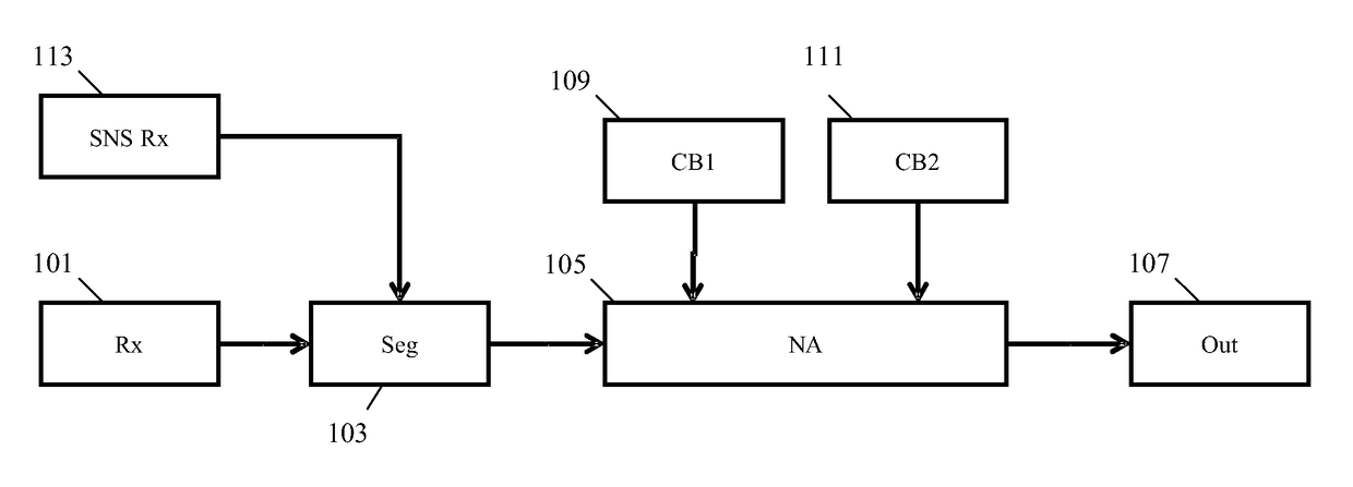
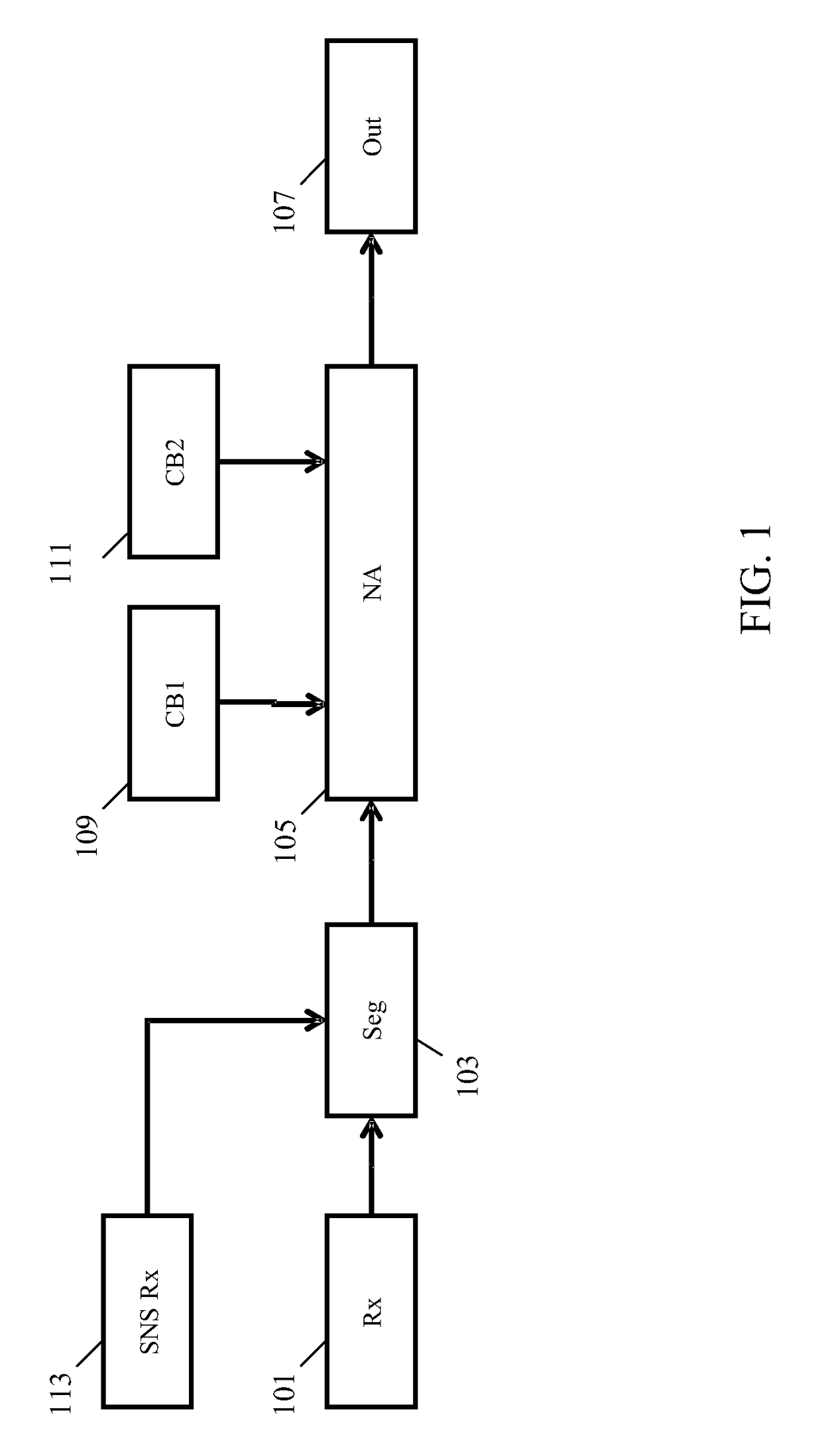
[0058]FIG. 1 illustrates an example of a noise attenuator in accordance with some embodiments of the invention.

[0059]The noise attenuator comprises a receiver 101 which receives a signal that comprises both a desired component and an undesired component. The undesired component is referred to as a noise signal and may include any signal component not being part of the desired signal component. The desired signal component corresponds to the sound generated from a desired sound source whereas the undesired or noise signal component may correspond to contributions from all other sound sources including diffuse and reverberant noise etc. The noise signal component may include ambient noise ...


PUM


Abstract

A noise attenuation apparatus receives a first signal comprising a desired and a noise signal component. Two codebooks (109, 111) comprise respectively desired signal candidates and noise signal candidates representing possible desired and noise signal components respectively. A noise attenuator (105) generates estimated signal candidates by for each pair of desired and noise signal candidates generating an estimated signal candidate as a combination of the desired signal candidate and the noise signal candidate. A signal candidate is then determined from the estimated signal candidates and the first signal is noise compensated based on this signal candidate. A sensor signal representing a measurement of the desired source or the noise in the environment is used to reduce the number of candidates searched thereby substantially reducing complexity and computational resource usage. The noise attenuation may specifically be audio noise attenuation.

Description

FIELD OF THE INVENTION[0001]The invention relates to signal noise attenuation and in particular, but not exclusively, to noise attenuation for audio and in particular speech signals.BACKGROUND OF THE INVENTION[0002]Attenuation of noise in signals is desirable in many applications to further enhance or emphasize a desired signal component. In particular, attenuation of audio noise is desirable in many scenarios. For example, enhancement of speech in the presence of background noise has attracted much interest due to its practical relevance.[0003]An approach to audio noise attenuation is to use an array of two or more microphones together with a suitable beam forming algorithm. However, such algorithms are not always practical or provide suboptimal performance. For example, they tend to be resource demanding and require complex algorithms for tracking a desired sound source. Also they tend to provide suboptimal noise attenuation in particular in reverberant and diffuse non-stationary ...

Claims


Application Information

Patent Timeline
Patent Type & Authority Patents(United States)
IPC IPC(8): G10L21/00G10L21/0216G10L21/0208
CPCG10L21/0208G10L21/0216G10L2021/02085G10L2021/02165G10L21/0364
Inventor KECHICHIAN, PATRICKSRINIVASAN, SRIRAM
Owner KONINKLJIJKE PHILIPS NV
Why Eureka
Try Eureka