Image pickup device and signal processing method

a pickup device and signal processing technology, applied in the field of image pickup devices and signal processing methods, can solve the problems of requiring a long time to raise detection accuracy, insufficient suppression of random noise output of each pixel, etc., and achieve the effects of short time, high accuracy and short tim

Inactive Publication Date: 2006-01-12
SONY CORP
View PDF6 Cites 19 Cited by
  • Summary
  • Abstract
  • Description
  • Claims
  • Application Information

AI Technical Summary

Benefits of technology

[0014] Hence, the present invention has been made to provide an image pickup device and a signal processing method thereof in which a column noise component is detected in a short time without being influenced under variant random noise even if the VOPB area B includes a small number of lines, and pixel signals from the effective pixel area A are corrected, based on the detected column noise component.
[0017] In the present invention, influences from random noise are suppressed, and such a combination of feedback coefficients that converges an integrated value to column noise is selected. In addition, a point at which the selected feedback coefficients are switched from each other is calculated, and a column noise component is detected, based on the calculation result. Therefore, a column noise component can be detected with high accuracy in a short time with a small number of lines. Further, with use of this highly accurate column noise component, column noise in pixel signals is corrected. Accordingly, images with high image quality can be provided.

Problems solved by technology

However, in case of obtaining a reference signal for correcting column noise by use of signals from the respective pixels in the VOPB area B, there is a significant problem of influence from a dark current component (hereinafter called random noise) which is outputted from each pixel in the VOPB area B and varies.
Therefore, even when an averaging processing is carried out, random noise outputted from each pixel cannot be suppressed sufficiently.
This method, however, requires a long time to raise the detection accuracy.

Method used


Image

  • Image pickup device and signal processing method
  • Image pickup device and signal processing method
  • Image pickup device and signal processing method

Examples


Embodiment Construction

[0030] Hereinafter, a description will be made of an image pickup device and a signal processing method according to an embodiment of the present invention.

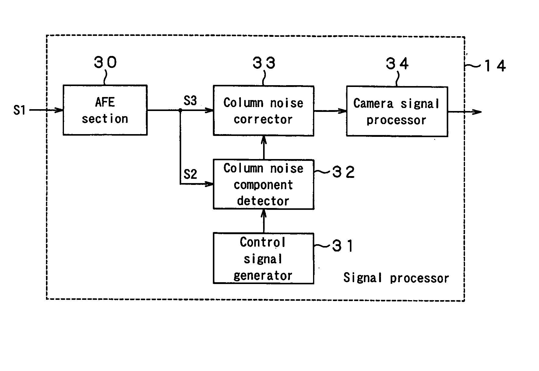
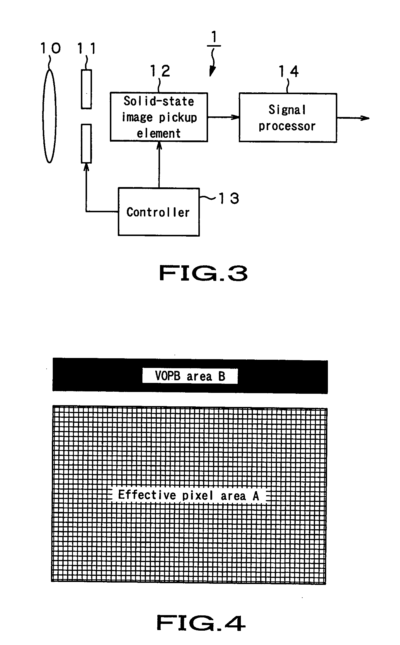
[0031] As shown in FIG. 3, an image pickup device 1 has: a lens 10 which converges incident light; a shutter 11 which allows light converged by the lens 10 to pass within the predetermined period of time; a solid-state image pickup element 12 which picks up an image of an object which enters as light through the lens 10 and the shutter 11; a controller 13 which controls the shutter 11 and the solid-state image pickup element 12; and a signal processor 14 which performs a predetermined signal processing on a pixel signal picked up by the solid-state image pickup element 12.

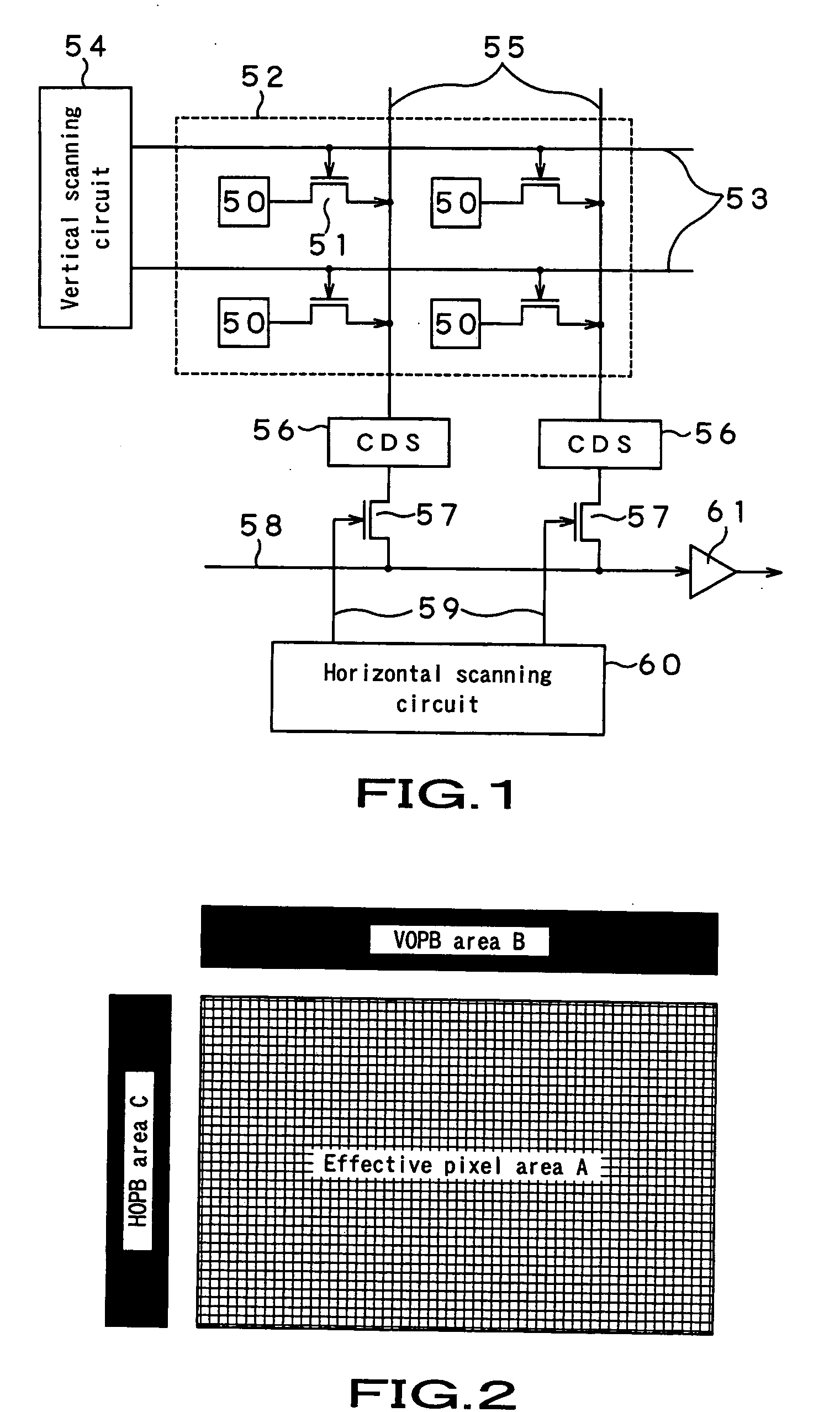
[0032] Light emitted from the object enters into the solid-state image pickup element 12 through an optical system including the lens 10 and the shutter 11. The solid-state image pickup element 12 has a pixel part which picks up an image of the object. As show...


PUM


Abstract

The present invention provides an image pickup device in which a column noise component is detected in a short time without being influenced under variant random noise even if the VOPB area B includes a small number of lines, and pixel signals from the effective pixel area A are corrected, based on the detected column noise component. The image pickup device includes a solid-state image pickup element having a pixel part including an effective pixel area to be irradiated with light, and a light-shielded pixel area where irradiation of light is shielded, a vertical scanning circuit, a horizontal scanning circuit, and an output circuit, a controller that controls the solid-state image pickup element such that the pixel signals outputted from the pixels arranged in the light-shielded pixel area or the pixel signals outputted from the pixels arranged in the effective pixel area are outputted from the output circuit, a control signal generator that generates a predetermined control signal, a noise component detector that detects noise, and a noise corrector that corrects noise contained in the pixel signals from the effective pixel area based on a noise component detected by the noise component detector, wherein the control signal generator generates different control signals at predetermined timing.

Description

CROSS REFERENCES TO RELATED APPLICATION [0001] The present invention contains subject matter related to Japanese Patent Application JP 2004-201014 filed in the Japanese Patent Office on Jul. 7, 2004, the entire contents of which being incorporated herein by reference. BACKGROUND OF THE INVENTION [0002] 1. Field of the Invention [0003] The present invention relates to an image pickup device which picks up an image of an object by use of an XY address type solid-state image pickup element, and a signal processing method for the image pickup device. [0004] 2. Description of the Related Art [0005] In a solid-state image pickup element 1 of an XY address type represented by a CMOS (complementary metal oxide semiconductor) sensor, a large number of pixels are arrayed in a matrix of lines and columns, as shown in FIG. 1. The element 1 has a vertical scanning circuit 54 to sequentially select lines of a pixel part 52, a horizontal scanning circuit 60 to sequentially select columns of the pi...

Claims


Application Information

Patent Timeline
Patent Type & Authority Applications(United States)
IPC IPC(8): H04N1/38H01L27/146H04N5/335H04N5/341H04N5/365H04N5/369H04N5/374
CPCH04N5/3658H04N5/361H04N25/63H04N25/677H04N25/60
Inventor INABA, SEIJIROTANAKA, KENJIMATSUI, AKIRAYONEDA, YUTAKA
Owner SONY CORP
Why Eureka
Try Eureka