Sample holder and analytical vacuum device

a vacuum device and sample holder technology, applied in the direction of measurement devices, electric discharge tubes, instruments, etc., can solve the problems of increasing the risk of damaging the sample, the sample holder cannot be easily altered, and the sample holder is easy to move, secure and easy to carry

Active Publication Date: 2018-01-23
HITACHI LTD
View PDF8 Cites 1 Cited by
  • Summary
  • Abstract
  • Description
  • Claims
  • Application Information

AI Technical Summary

Benefits of technology

[0020]Using a sample holder and an analytical vacuum device according to the present invention enables performing elemental analysis to a material that easily alters due to atmospheric exposure. In addition, sample transferring can be secure and easy between an FIB device, a scanning electron microscope (SEM), a TEM, and an analysis device such as atom probe, from needle-shaped sample processing to measurement.
[0021]Problems, configurations, and effects other than the above descriptions will be clarified by the following embodiments.

Problems solved by technology

However, only the FIB cannot often ascertain whether a leading end of the needle-shaped sample that has been completed actually includes a region to be analyzed.
Thus, a risk of damaging the sample increases.

Method used


Image

  • Sample holder and analytical vacuum device
  • Sample holder and analytical vacuum device
  • Sample holder and analytical vacuum device

Examples


first embodiment

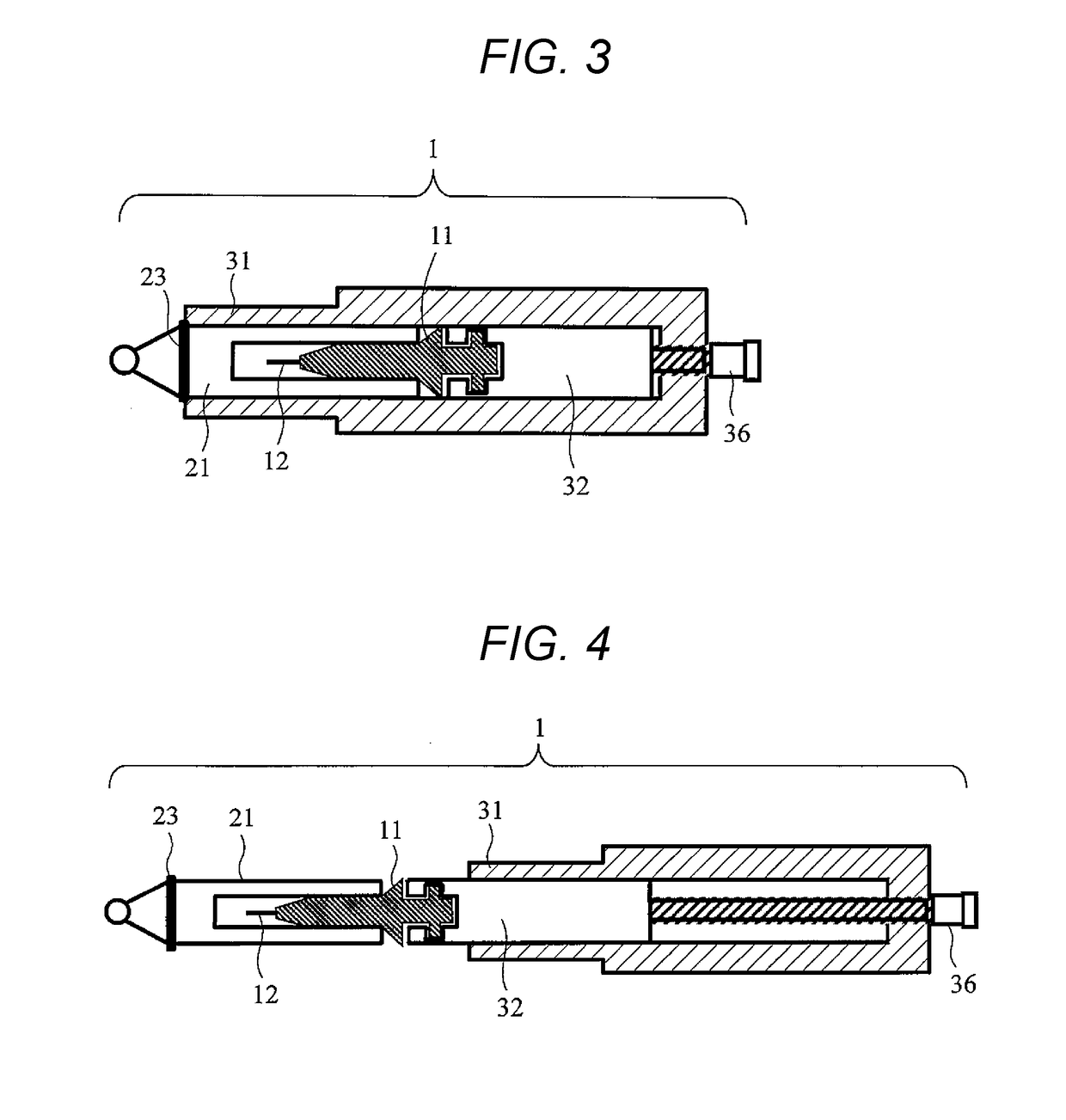
[0036]FIG. 4 is a cross-sectional schematic view of a structure of an entire sample holder 1 according to a first embodiment of the present invention. The sample holder 1 includes four parts: a sample base 11, a housing 21, a cylindrical body 31 having one end open, and a drive support portion 32 capable of translational motion inside the cylindrical body 31. By operating a micrometer 36, the drive support portion 32 is translated in a direction in which the drive support portion 32 protrudes from the cylindrical body 31 or in a direction in which the drive support portion 32 is introduced to the inside of the cylindrical body 31. The housing 21 and the sample base 11 include structures that couple to each other so as to be attachable and detachable. The sample base 11 and the drive support portion 32 include structures that couple to each other so as to be attachable and detachable. The sample base 11 holds a needle-shaped sample 12. The housing 21 has a substantially U-shaped fram...

second embodiment

[0051]FIG. 9 is an exploded perspective view of a structure of a sample holder leading end according to a second embodiment of the present invention. A leading end portion of the sample holder includes four members: a sample base 11, a housing 21, a cylindrical body 31, and a drive support portion 32. According to the second embodiment, the housing 21 is coupled to the drive support portion 32 in a “rotation” manner and the sample base 11 is coupled to the drive support portion 32 in a “translation+rotation” manner.

[0052]As illustrated in FIG. 9, a leading end portion of the drive support portion 32 has a male screw structure 14 on an outer surface. The housing 21 has a female screw structure 22 on an inner surface. The housing 21 and the drive support portion 32 have the structures so as to be coupled to each other by rotation around a holder axis. The leading end portion of the drive support portion 32 has a cylindrical recess portion into which a tail end portion of the sample ba...

third embodiment

[0060]FIG. 12 is a cross-sectional schematic view of a structure of a sample base 11 having a sample rotating mechanism according to a third embodiment of the present invention. The sample base 11 according to the present embodiment includes an external cylinder 53 and a rotary internal cylinder 51. The external cylinder 53 includes a protrusion 13 disposed thereon. The rotary internal cylinder 51 has a sample holding portion 15 at a leading end thereof. A needle-shaped sample 12 can be fixed to the rotary internal cylinder 51. A groove 52 at a tail end of the rotary internal cylinder 51 is used and axial rotation of the rotary internal cylinder 51 is performed with respect to the external cylinder 53 of the sample base 11. Thus, axial rotation of the needle-shaped sample 12 can be performed. Accordingly, an incident direction of a charged particle beam with respect to the needle-shaped sample 12 can be changed. Note that, the groove 52 that rotates the rotary internal cylinder 51, ...


PUM

PropertyMeasurementUnit
electric fieldaaaaaaaaaa
diameteraaaaaaaaaa
atomic arrangement/composition distributionaaaaaaaaaa

Abstract

Sample transferring can be securely and easily performed between an FIB device, an electron microscope, and an atom probe device, and atom probe analysis can be performed to a material that easily alters due to atmospheric exposure. A sample holder that holds a sample (12) is provided with an atmosphere-isolation mechanism that prevents the sample from altering due to the atmospheric exposure upon the sample transferring between the devices. There is provided a structure enabling of attaching and detaching a housing (21) of a sample holder leading end of a part of the atmosphere-isolation mechanism in an analytical vacuum device, such as the atom probe device.

Description

TECHNICAL FIELD[0001]The present invention relates to a sample holder for a charged particle beam device, and an analytical vacuum device, such as an atom probe device, which analyzes a sample by using the sample holder.BACKGROUND ART[0002]Atom probe is an analytical method capable of directly observing atomic arrangement / composition distribution of a leading end of a sample that has been processed so as to be needle-shaped, at an atomic scale. In the atom probe, a high direct current voltage is applied so as to cause the leading end of the needle-shaped sample to generate a high electric field. A pulse voltage is applied or a pulse laser is irradiated to the leading end so that field evaporation of an atom belonging to a first layer of a surface is induced. Then, mass of an ion that has field-evaporated is time-of-flight-measured so that a type of an element can be determined. Since the field evaporation progresses every atomic layer, atom probe analysis has resolution in a depth d...

Claims


Application Information

Patent Timeline
Patent Type & Authority Patents(United States)
IPC IPC(8): H01J37/18G01N23/22H01J37/20H01J37/285
CPCH01J37/185G01N23/2204H01J37/285H01J37/20H01J2237/204H01J2237/184
Inventor NAKAYAMA, TAKESHIHASHIZUME, TOMIHIROSUGAWARA, AKIRA
Owner HITACHI LTD
Why Eureka
Try Eureka