Sample holder and analytical vacuum device
a vacuum device and sample holder technology, applied in the direction of measurement devices, electric discharge tubes, instruments, etc., can solve the problems of increasing the risk of damaging the sample, the sample holder cannot be easily altered, and the sample holder is easy to move, secure and easy to carry
- Summary
- Abstract
- Description
- Claims
- Application Information
AI Technical Summary
Benefits of technology
Problems solved by technology
Method used
Image
Examples
first embodiment
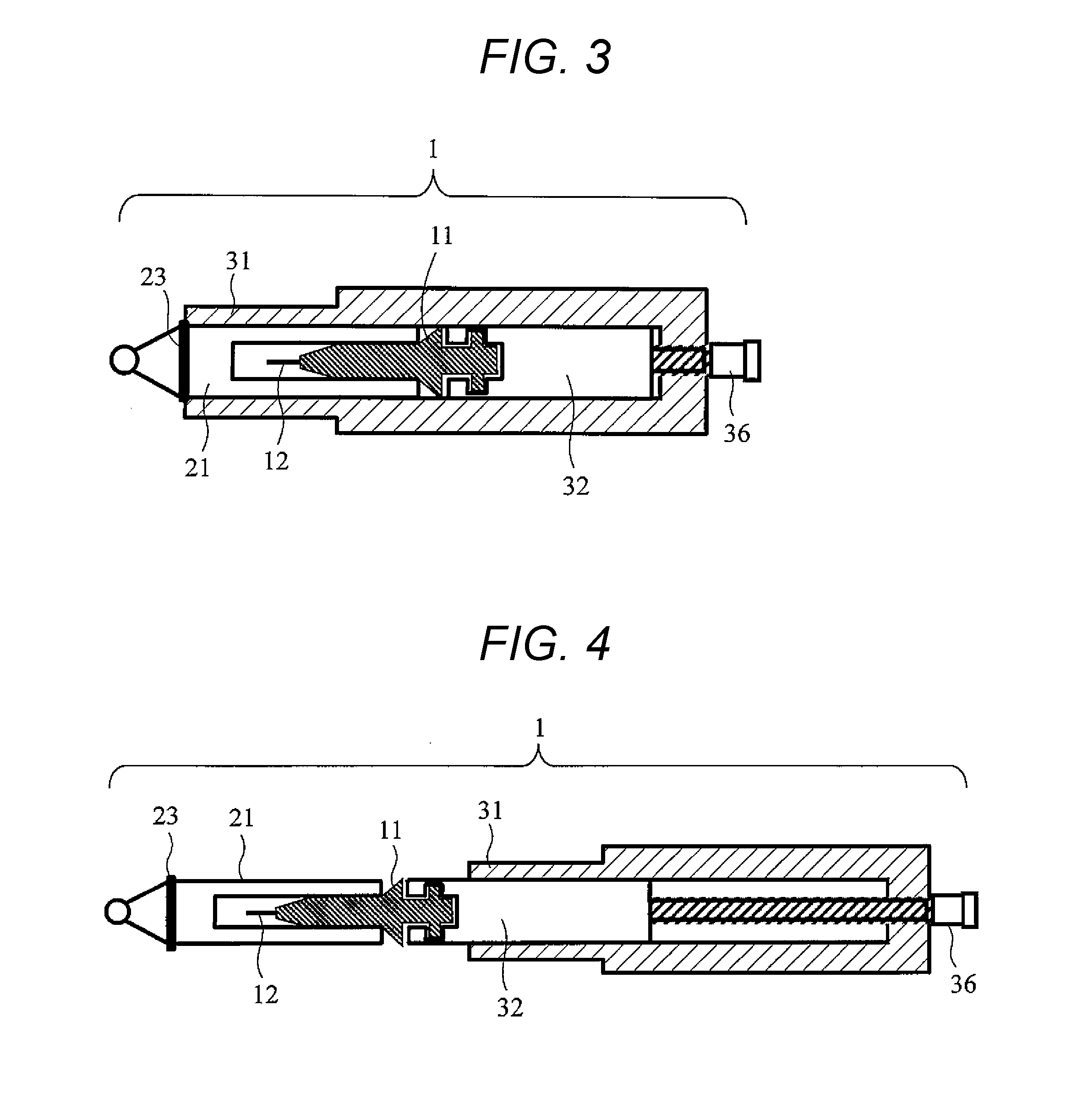
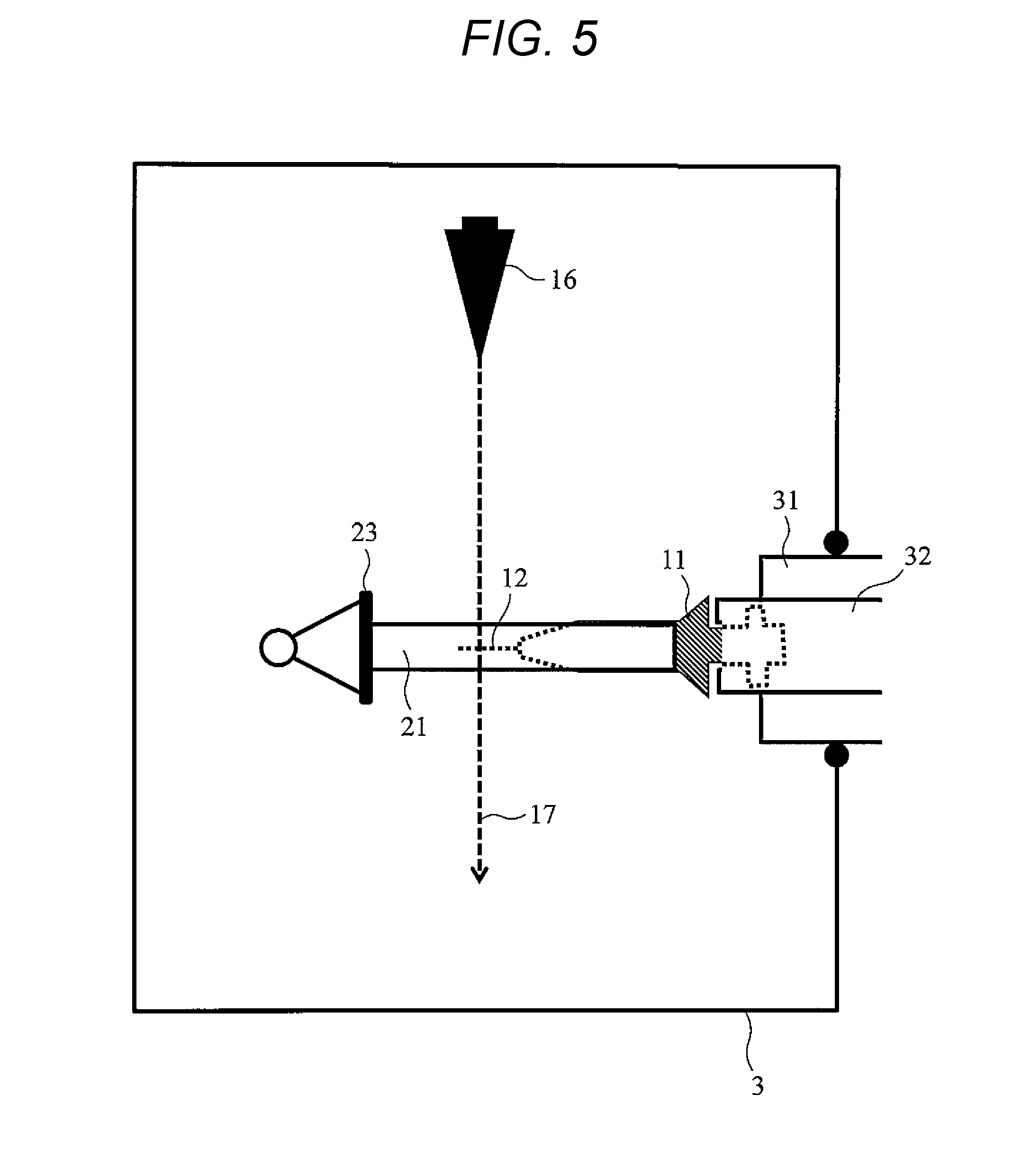
[0036]FIG. 4 is a cross-sectional schematic view of a structure of an entire sample holder 1 according to a first embodiment of the present invention. The sample holder 1 includes four parts: a sample base 11, a housing 21, a cylindrical body 31 having one end open, and a drive support portion 32 capable of translational motion inside the cylindrical body 31. By operating a micrometer 36, the drive support portion 32 is translated in a direction in which the drive support portion 32 protrudes from the cylindrical body 31 or in a direction in which the drive support portion 32 is introduced to the inside of the cylindrical body 31. The housing 21 and the sample base 11 include structures that couple to each other so as to be attachable and detachable. The sample base 11 and the drive support portion 32 include structures that couple to each other so as to be attachable and detachable. The sample base 11 holds a needle-shaped sample 12. The housing 21 has a substantially U-shaped fram...
second embodiment
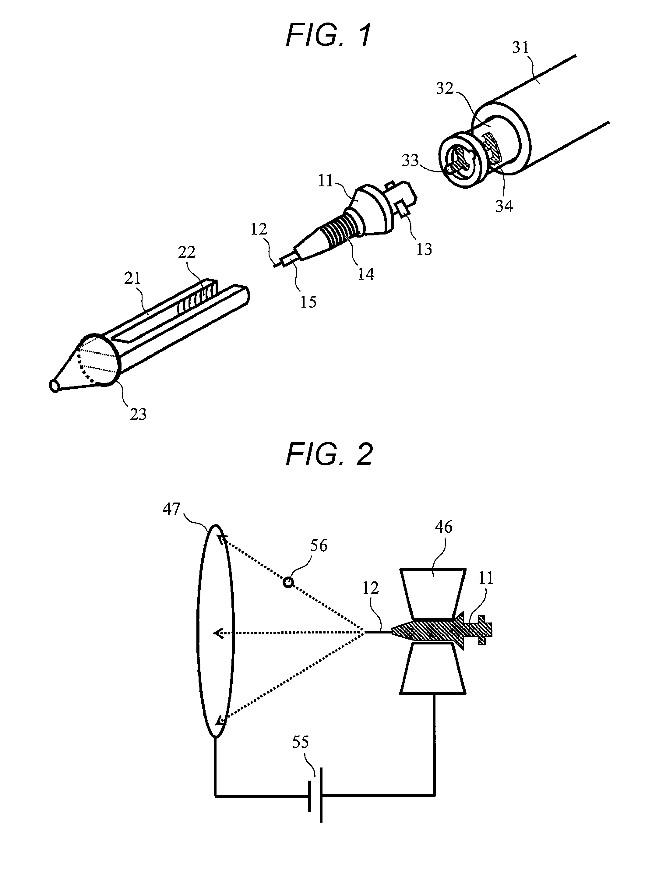
[0051]FIG. 9 is an exploded perspective view of a structure of a sample holder leading end according to a second embodiment of the present invention. A leading end portion of the sample holder includes four members: a sample base 11, a housing 21, a cylindrical body 31, and a drive support portion 32. According to the second embodiment, the housing 21 is coupled to the drive support portion 32 in a “rotation” manner and the sample base 11 is coupled to the drive support portion 32 in a “translation+rotation” manner.
[0052]As illustrated in FIG. 9, a leading end portion of the drive support portion 32 has a male screw structure 14 on an outer surface. The housing 21 has a female screw structure 22 on an inner surface. The housing 21 and the drive support portion 32 have the structures so as to be coupled to each other by rotation around a holder axis. The leading end portion of the drive support portion 32 has a cylindrical recess portion into which a tail end portion of the sample ba...
third embodiment
[0060]FIG. 12 is a cross-sectional schematic view of a structure of a sample base 11 having a sample rotating mechanism according to a third embodiment of the present invention. The sample base 11 according to the present embodiment includes an external cylinder 53 and a rotary internal cylinder 51. The external cylinder 53 includes a protrusion 13 disposed thereon. The rotary internal cylinder 51 has a sample holding portion 15 at a leading end thereof. A needle-shaped sample 12 can be fixed to the rotary internal cylinder 51. A groove 52 at a tail end of the rotary internal cylinder 51 is used and axial rotation of the rotary internal cylinder 51 is performed with respect to the external cylinder 53 of the sample base 11. Thus, axial rotation of the needle-shaped sample 12 can be performed. Accordingly, an incident direction of a charged particle beam with respect to the needle-shaped sample 12 can be changed. Note that, the groove 52 that rotates the rotary internal cylinder 51, ...
PUM
 Abstract
Description
Claims
Application Information
 - R&D
- Intellectual Property
- Life Sciences
- Materials
- Tech Scout
- Unparalleled Data Quality
- Higher Quality Content
- 60% Fewer Hallucinations
Browse by: Latest US Patents, China's latest patents, Technical Efficacy Thesaurus, Application Domain, Technology Topic, Popular Technical Reports.
© 2025 PatSnap. All rights reserved.Legal|Privacy policy|Modern Slavery Act Transparency Statement|Sitemap|About US| Contact US: help@patsnap.com


