
Aircraft

a propulsion unit and aircraft technology, applied in aircrafts, vertical landing/take-off aircraft, transportation and packaging, etc., can solve the problems of not so well known combinations of the two, and the fuselage has never been intentionally rotated along with its airfoil(s)

Active Publication Date: 2018-01-30
ADVISR AERO LLC
View PDF15 Cites 5 Cited by
  • Summary
  • Abstract
  • Description
  • Claims
  • Application Information

AI Technical Summary

Benefits of technology

The present invention is an aircraft that can be flown either as a fixed wing aircraft or as a rotating body. It has a unique design with outboard wing portions that can be flipped to change between fixed wing and rotary wing configurations. The aircraft can also be equipped with thrusters that generate forces in opposite directions for both fixed and rotary wing flight. The controller on the base member is responsible for flipping the outboard wing portion and controlling the forces exerted by the thrusters. The technical effects of the invention include the ability for the aircraft to switch between fixed and rotary wing configurations, and the ability to generate forces in opposite directions for both types of flight.

Problems solved by technology

While both rotary wing and fixed wing aircraft have been commonplace for quite some time, and although the underlying aerodynamics for each type aircraft can be separately appreciated, different combinations of the two are not so well known.
Heretofore, however, the fuselage has never been intentionally rotated along with its airfoil(s).

Method used


Image

  • Aircraft
  • Aircraft
  • Aircraft

Examples


Embodiment Construction

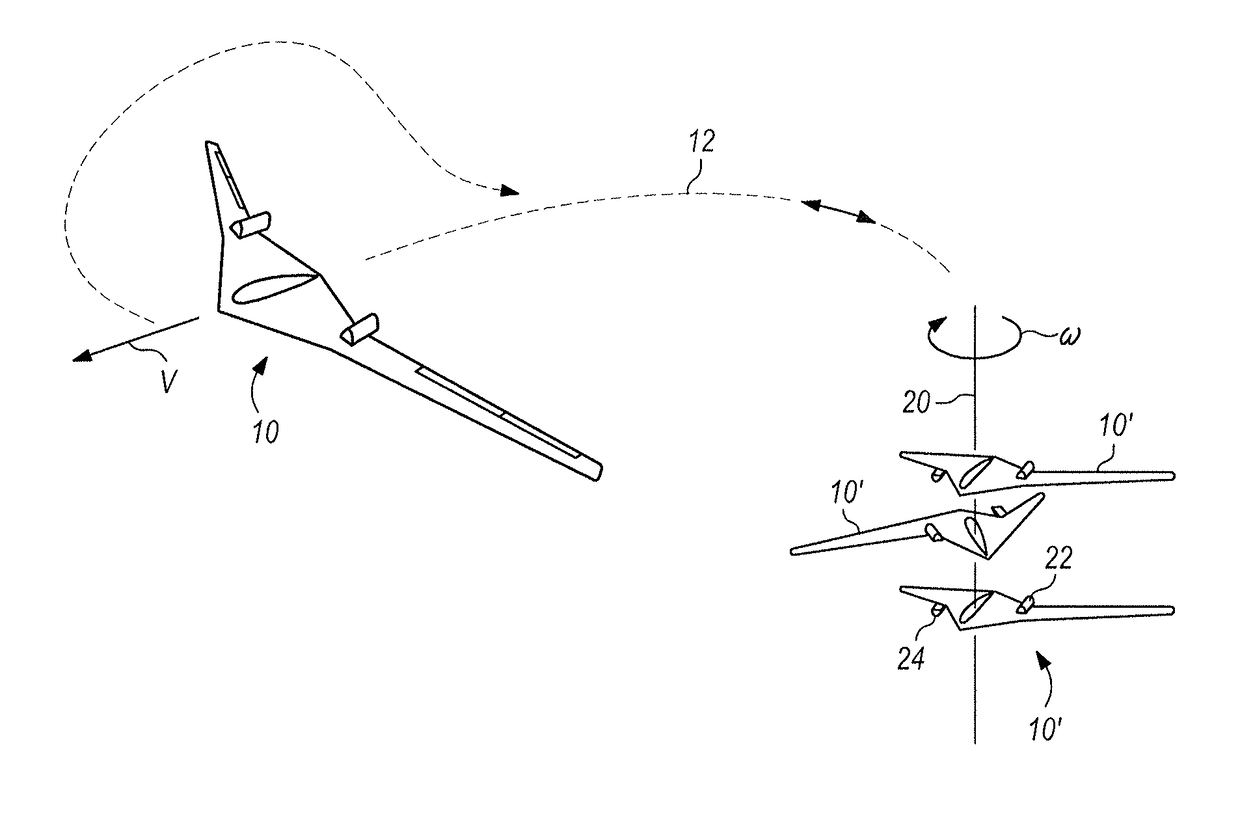
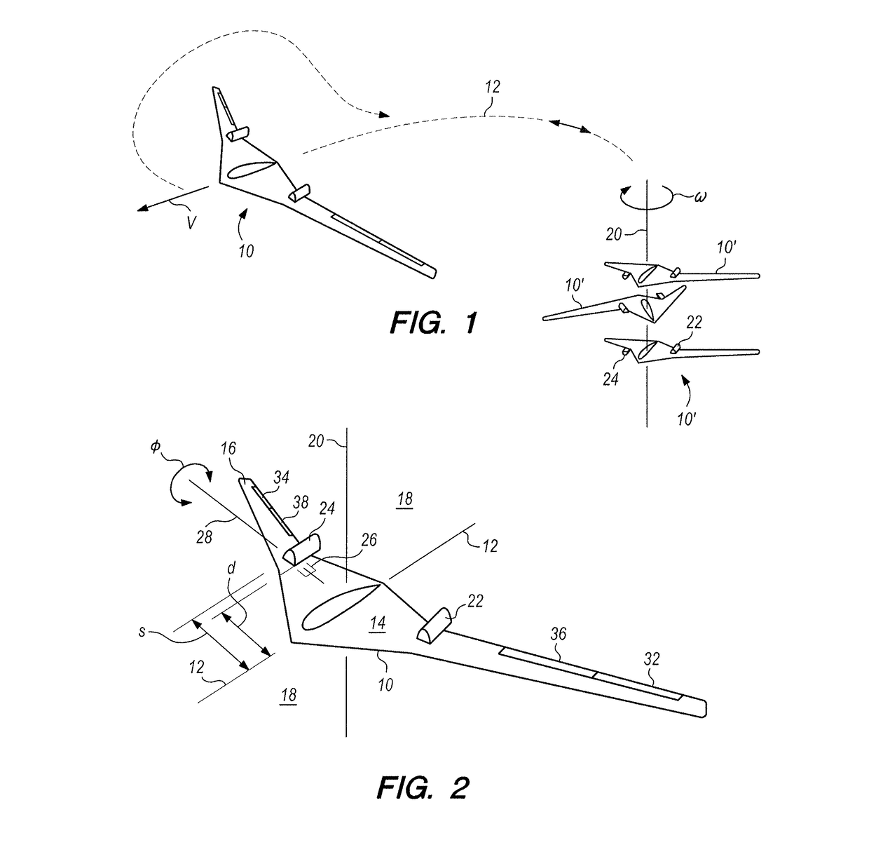
[0022]Referring initially to FIG. 1 an aircraft in accordance with the present invention is shown, and depending on its configuration is generally designated 10 or 10′. More particularly, the aircraft 10 is shown flying on a typical flight path 12 that requires both rotary wing and fixed wing flight capabilities. As shown in FIG. 1, and for disclosure purposes only, the aircraft when designated 10 will be generally considered as being in a fixed wing configuration (this configuration is hereinafter sometimes referred to as “F”). On the other hand, when designated 10′ it will be generally considered that the aircraft 10′ is in the rotary wing configuration (this configuration is hereinafter sometimes referred to as “R”). As also indicated in FIG. 1, rotary wing flight for the aircraft 10′ will require the entire aircraft 10′ to be rotated, in R, at an angular velocity, ω. For F, however, ω=0. In either configuration, aircraft 10′ (R), as well as aircraft 10 (F), will both have a flig...


PUM


Abstract

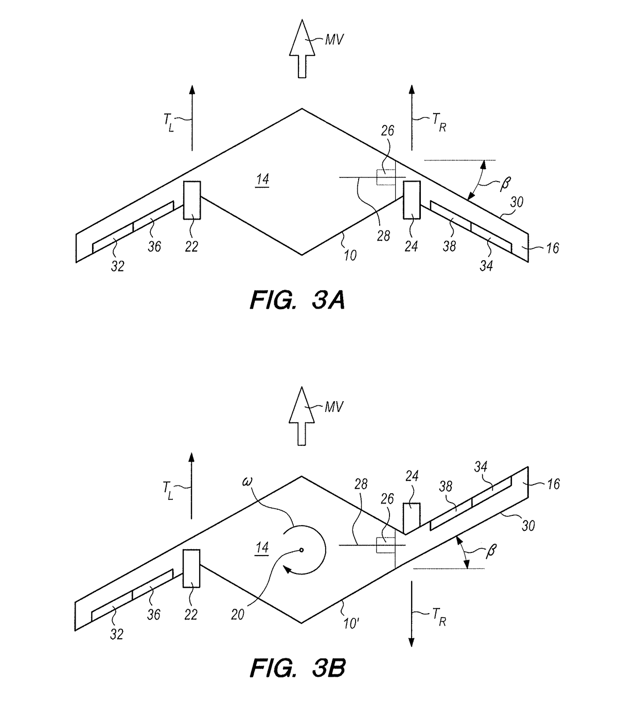
An aircraft is provided that is convertible in flight between a rotary wing configuration and a fixed wing configuration. In its fixed wing configuration the aircraft resembles a Blended Wing Body (BWB) having a swept wing angle β. Conversions from the fixed wing configuration to the rotary wing configuration, and vice versa, are accomplished by flipping an outboard portion of one wing through 180° to reorient the leading edge of the outboard portion by an angle of 2β to establish a reverse sweep. In its rotary configuration, the entire aircraft is rotated.

Description

FIELD OF THE INVENTION[0001]The present invention pertains generally to aerodynamic configurations and propulsion units for aircraft. In particular, the present invention pertains to aircraft that fly in either a rotary wing configuration or a fixed wing configuration. The present invention is particularly, but not exclusively, useful as an aircraft that can be converted in flight between its rotary wing and fixed wing configurations, and wherein for the rotary wing configuration the entire aircraft is rotated.BACKGROUND OF THE INVENTION[0002]While both rotary wing and fixed wing aircraft have been commonplace for quite some time, and although the underlying aerodynamics for each type aircraft can be separately appreciated, different combinations of the two are not so well known. Various aircraft designs which can fly both vertically and horizontally have generally fallen under the rubric of Vertical Takeoff and Landing (VTOL) aircraft. Helicopters are the most common configuration ...

Claims


Application Information

Patent Timeline
Patent Type & Authority Patents(United States)
IPC IPC(8): B64C27/16B64C39/10B64C37/00B64C27/24B64C3/38B64C27/18B64C29/00
CPCB64C39/10B64C3/38B64C27/16B64C27/24B64C29/0075B64C37/00B64C27/18B64C2039/105
Inventor BLUE, LINDEN S.BLUE, AUSTIN J. N.
Owner ADVISR AERO LLC
Learn More