
Compressor guide-vane stage for a turbine engine including a gasket between a vane and a shroud of the guide-vane stage

a turbine engine and compressor technology, applied in the direction of machines/engines, stators, liquid fuel engines, etc., can solve the problems of complex resin batch management, long and expensive injection steps, and difficult, dirtying, etc., and achieve the effect of simple, effective and inexpensive solutions

Active Publication Date: 2018-01-30
SN DETUDE & DE CONSTR DE MOTEURS DAVIATION S N E C M A
View PDF13 Cites 0 Cited by
  • Summary
  • Abstract
  • Description
  • Claims
  • Application Information

AI Technical Summary

Benefits of technology

The present invention offers a better solution to the issue of leakage in a low-cost manner. It eliminates the need for an injection step and replaces it with a simpler step in which gaskets are mounted on the vanes to prevent resin from leaking through the clearance and running out into the guide-vane stage. The gaskets are designed to be embedded in the resin, which hardens to form a seal between the vanes and the inner surface of the inner shroud. A substance may be coated on the inner surface of the inner shroud to enhance the adhesion of the gaskets. This solution provides improved efficiency and ease of use in the manufacturing process of a low-cost gas turbine engine.

Problems solved by technology

At present, resin is injected into the clearance by means of a syringe that is filled by an operator, with this injection step being lengthy and expensive (taking about 8 hours for one guide-vane stage), difficult, dirtying, and poorly reproducible.
Nevertheless, although that makes it easier to work the resin, it involves complex management of batches of resin.

Method used


Image

  • Compressor guide-vane stage for a turbine engine including a gasket between a vane and a shroud of the guide-vane stage
  • Compressor guide-vane stage for a turbine engine including a gasket between a vane and a shroud of the guide-vane stage
  • Compressor guide-vane stage for a turbine engine including a gasket between a vane and a shroud of the guide-vane stage

Examples


Embodiment Construction

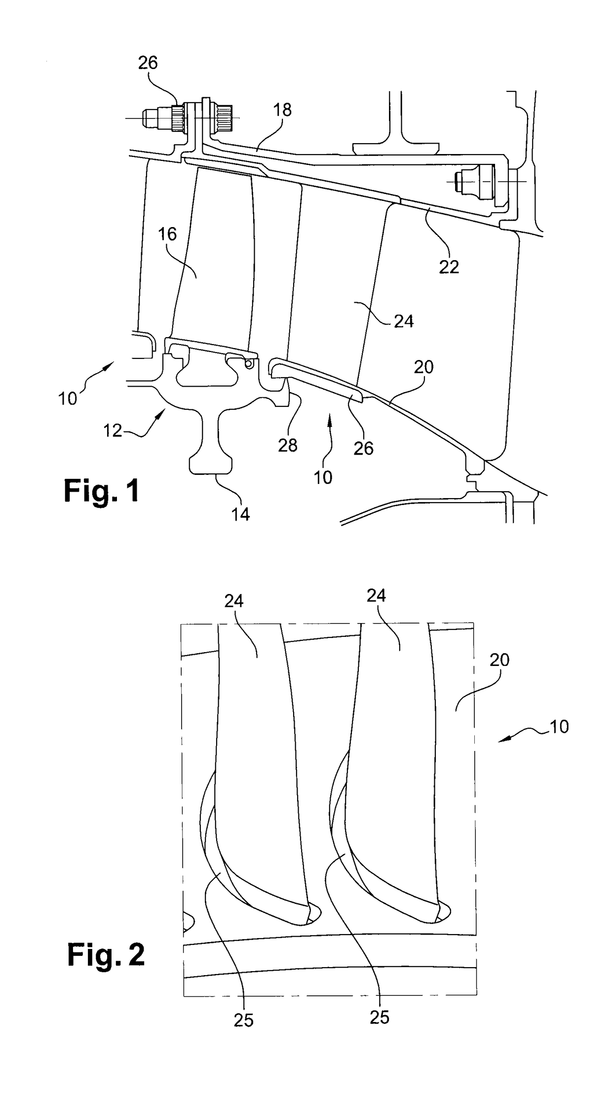
[0035]Reference is made initially to FIG. 1, which shows a low-pressure compressor of a turbine engine such as an airplane turbojet or turboprop, the compressor having guide-vane stages 10 with moving-blade stages 12 located between them.

[0036]Each moving-blade stage 12 comprises a disk 14 carrying an angular row of substantially radial blades 16 at its periphery, the blades being surrounded by a casing 18 of the compressor.

[0037]Each guide-vane stage 10 comprises two shrouds, respectively an inner shroud 20 and an outer shroud 22, between which there extends an annular row of substantially radial vanes 24, the outer shroud 22 being fastened to the casing 18 by nut-and-bolt type means 26.

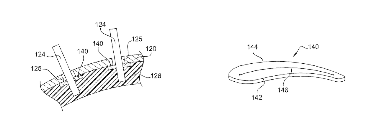
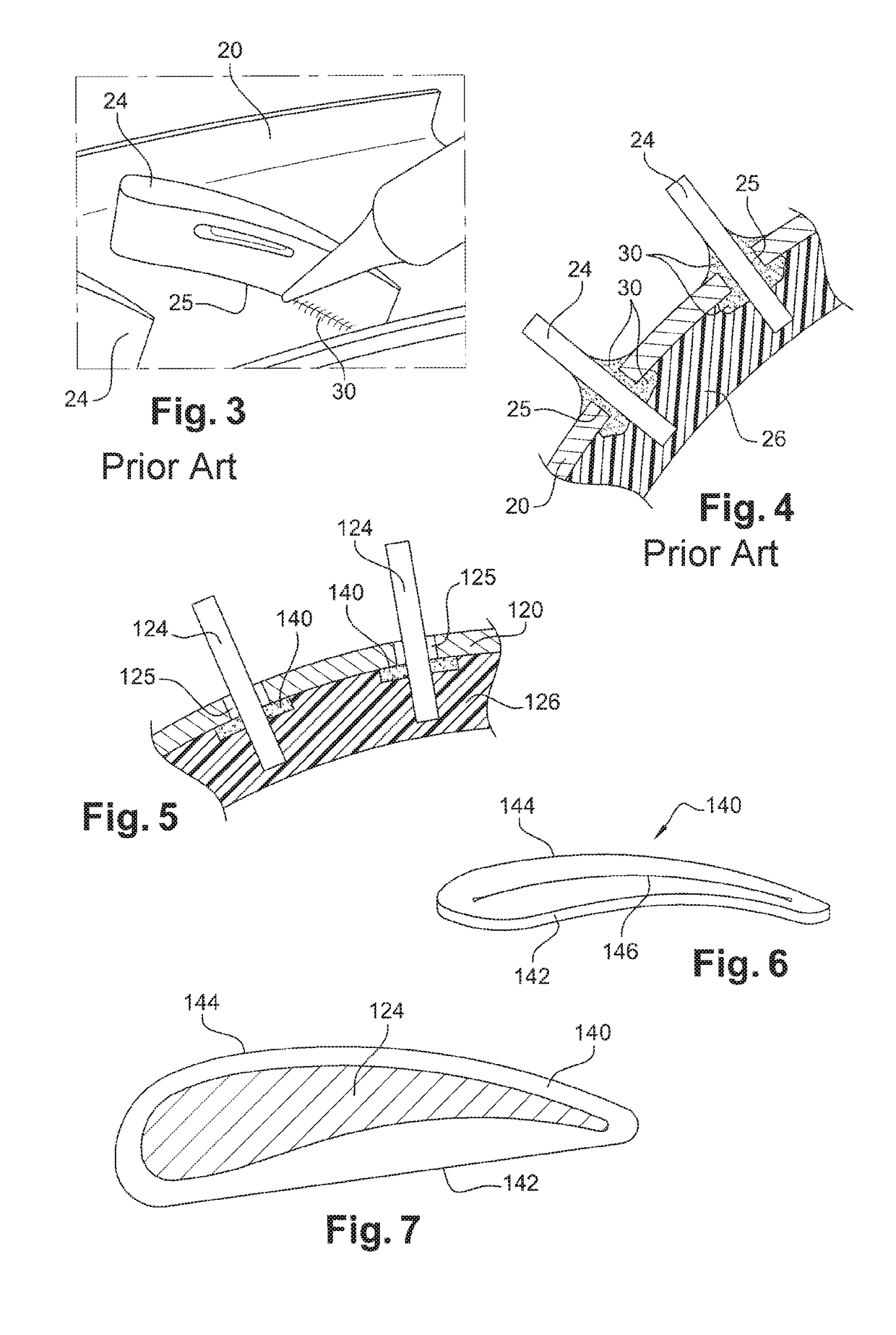
[0038]The radially outer ends of the vanes 24 are welded to the outer shroud 22. The radially inner ends of the vanes 24 are engaged with clearance 25 in orifices of the inner shroud 20 (FIG. 2) and they are secured to the inner shroud 20 by applying a polymerizable sealing resin 26 on the radially ...


PUM

PropertyMeasurementUnit
thicknessaaaaaaaaaa
thicknessaaaaaaaaaa
pressureaaaaaaaaaa

Abstract

A compressor guide-vane stage for a turbine engine, the stage comprising two coaxial shrouds, respectively an inner shroud (120) and an outer shroud, with vanes (124) extending between them, the radially inner ends of the vanes being engaged with clearance (125) in orifices in the inner shroud and being secured to the inner shroud by means of a polymerizable sealing resin (126), the guide-vane stage being characterized in that a gasket (140) is mounted on the radially inner end of each vane, the gasket including a slit through which the vane passes and bearing against the radially inside surface of the shroud or in the proximity of said surface, in order to limit the passage of resin through the above-mentioned clearance while the resin is being applied to the inside surface of the shroud.

Description

BACKGROUND OF THE INVENTION[0001]Field of the Invention[0002]The present invention relates to a compressor guide-vane stage for a turbine engine, in particular for a low-pressure compressor of a turbine engine.[0003]Description of the Related Art[0004]A turbine engine compressor includes at least one guide-vane stage comprising two coaxial shrouds extending one inside the other with substantially radial vanes extending between them, which vanes are connected at their radial ends to the shroud.[0005]The outer shroud of a guide-vane stage has radial orifices in which the radially outer ends of the vanes are engaged and fastened, generally by welding. The inner shroud of the guide-vane stage has radial orifices in which the radially inner ends of the vanes are engaged with clearance, such clearance being of the order of 2 millimeters (mm) to 3 mm, approximately.[0006]In the prior art, the inner ends of the vanes are secured to the inner shroud by means of a polymerizable sealing resin ...

Claims


Application Information

Patent Timeline
Patent Type & Authority Patents(United States)
IPC IPC(8): F01D25/00F04D19/02F04D29/08F04D29/54
CPCF01D25/00F04D19/022F04D29/542F04D29/083Y10T29/49238F01D5/22F01D5/26F01D5/30F01D9/042
Inventor VATIN, ERIC RAYMOND JEAN
Owner SN DETUDE & DE CONSTR DE MOTEURS DAVIATION S N E C M A
Learn More