Tool and method for implanting fusion device into sacroiliac joint

a fusion device and tool technology, applied in the field of surgical instruments and methods, can solve the problems of reducing the recovery time required for surgery, reducing the surgical efficiency of surgeons,

Active Publication Date: 2018-02-06
VG INNOVATIONS
View PDF59 Cites 15 Cited by
  • Summary
  • Abstract
  • Description
  • Claims
  • Application Information

AI Technical Summary

Benefits of technology

[0016]Another important object is to provide tools that produce consistent results from patient to patient.

Problems solved by technology

Placing a fusion implant into the sacroiliac area is difficult because the ilium protrudes and blocks easy access to the site.
Part of the ilium can be cut and removed to improve access, but such cutting weakens the ilium, extends the time required for surgery and recovery from surgery, and increases the patient's pain.

Method used


Image

  • Tool and method for implanting fusion device into sacroiliac joint
  • Tool and method for implanting fusion device into sacroiliac joint
  • Tool and method for implanting fusion device into sacroiliac joint

Examples


Embodiment Construction

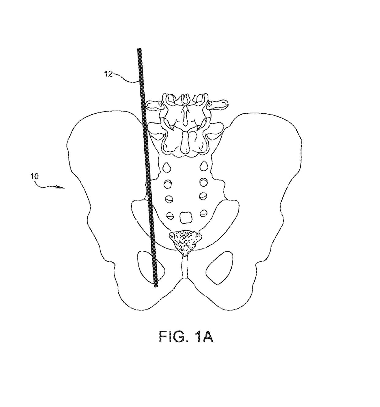
[0057]FIGS. 1A-8D depict an illustrative embodiment of the novel instrument and the novel method steps with which it is used. The sacroiliac (SI) joint of a patient is denoted as a whole by the reference numeral 10.

[0058]The novel method steps include the steps of taking anterior, posterior, and lateral X-ray views of the sacroiliac (SI) area to identify the anatomy that is causing pain in a patient.

[0059]An entry point is established to gain access to the SI joint with an oblique (approximately thirty five degree (35°) angle) and a Ferguson angle measurement of curvature which is approximately ten to fifteen degrees (10-15°).

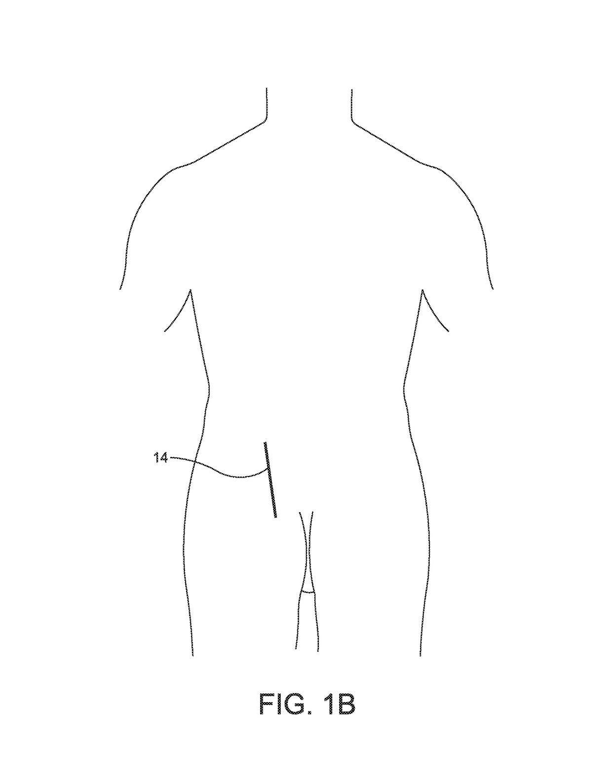
[0060]As depicted in FIG. 1A, first guide wire 12 is placed on top of the SI joint and as depicted in FIG. 1B, the patient's skin is marked with a first straight line 14 to indicate the position of first guide wire 12. First straight line 14 is drawn through SI joint 10 from the superior position of the joint to the inferior position of the joint.

[0061]As depic...


PUM


Abstract

Tools for positioning an implant into the sacroiliac joint. A directional cannula includes a main body having a bore that receives the implant. A cut-out, allowing access to the joint, is formed in a leading end of the main body. A pair of parallel prongs extend from the leading end of the main body in transversely spaced apart relation to one another. A drill guide has a main body of rectangular transverse cross-section and a cylindrical head formed integrally with the main body. A transverse width-reducing step is formed in the main body near its distal end. First and second bores are formed in the cylindrical head and in the main body. Both bores are eccentric relative to the drill guide longitudinal axis of symmetry. The drill guide is rotated 180° after first and second drilling operations, prior to third and fourth drilling operations.

Description

BACKGROUND OF THE INVENTION1. Field of the Invention[0001]This invention relates, generally, to surgical instruments and methods. More particularly, it relates to a tool for introducing a fusion device, also known as an implant or fusion implant, into a sacroiliac joint.2. Description of the Prior Art[0002]Placing a fusion implant into the sacroiliac area is difficult because the ilium protrudes and blocks easy access to the site. Part of the ilium can be cut and removed to improve access, but such cutting weakens the ilium, extends the time required for surgery and recovery from surgery, and increases the patient's pain.[0003]New tools are needed that would eliminate the need to cut the ilium.[0004]However, in view of the art considered as a whole at the time the present invention was made, it was not obvious to those of ordinary skill in the art how the needed tools could be provided.SUMMARY OF THE INVENTION[0005]The long-standing but heretofore unfulfilled need for a device that ...

Claims


Application Information

Patent Timeline
Patent Type & Authority Patents(United States)
IPC IPC(8): A61B17/17A61F2/46A61B17/88A61B17/90
CPCA61B17/17A61B17/8894A61B17/1739A61F2/4603A61B17/1757A61F2/4611A61B2017/90A61B17/7055A61B17/90
Inventor VESTGAARDEN, TOV INGE
Owner VG INNOVATIONS
Why Eureka
Try Eureka