
Electronic vehicle pedal activation system

a technology of electronic vehicle pedals and actuators, applied in the direction of gearing, mechanical control devices, instruments, etc., can solve the problem of not disclosing a new electronic vehicle pedal activation system, and achieve the effect of convenient and quick setup

Inactive Publication Date: 2018-02-06
BUSE TIMOTHY
View PDF20 Cites 4 Cited by
  • Summary
  • Abstract
  • Description
  • Claims
  • Application Information

AI Technical Summary

Benefits of technology

The present invention provides an electronic vehicle pedal activation system that allows for easy and quick setup in the passenger compartment, remote control, and individual control of the amount of pedal depressed, retracted, or released. This system eliminates the need for more than one person to work on a vehicle and improves overall efficiency.

Problems solved by technology

While these devices fulfill their respective, particular objectives and requirements, the aforementioned patents do not disclose a new electronic vehicle pedal activation system.

Method used


Image

  • Electronic vehicle pedal activation system
  • Electronic vehicle pedal activation system
  • Electronic vehicle pedal activation system

Examples


Embodiment Construction

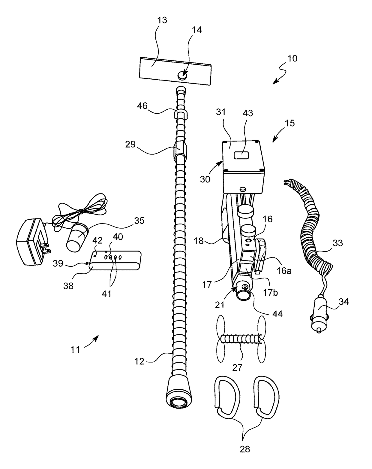
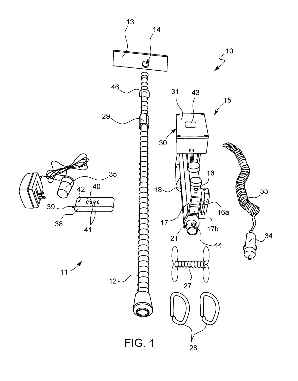
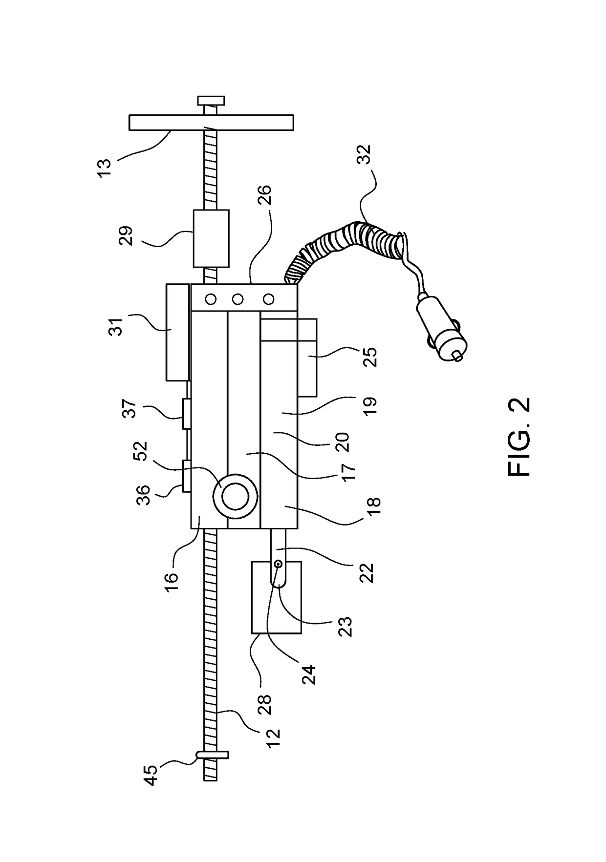
[0018]With reference now to the drawings, and in particular to FIGS. 1 through 5 thereof, a new electronic vehicle pedal activation system embodying the principles and concepts of the present invention and generally designated by the reference numeral 10 will be described.

[0019]As best illustrated in FIGS. 1 through 5, the electronic vehicle pedal activation system 10 may generally comprise a support assembly 10 including a shaft 12 having a length and adapted to be removable and in contactable relationship with a floor board 49 of a vehicle; and may also comprise a pedal activation assembly 15 in communication with the support assembly 11 for moving a pedal 50 of a vehicle; and may further comprise a control assembly 30 in operable communication with the pedal activation assembly 15. The support assembly 11 may also include a brace 13 conventionally movable and engagable upon and along the shaft 13 and adapted to engage the seat 48 of a vehicle to secure the shaft 12 inside a passe...


PUM


Abstract

An electronic vehicle pedal activation system for eliminating the need to have more than one person when working on vehicle where using a pedal of the vehicle is required. The electronic vehicle pedal activation system includes a support assembly including a shaft having a length and adapted to be removable and in contactable relationship with a floor board; a pedal activation assembly in communication with the support assembly for moving a pedal of a vehicle; and a control assembly in operable communication with the pedal activation assembly.

Description

BACKGROUND OF THE INVENTIONField of the Invention[0001]The present invention relates to vehicle pedal actuator and more particularly pertains to a new electronic vehicle pedal activation system for eliminating the need to have more than one person when working on a vehicle where using a vehicle pedal is required.Description of the Prior Art[0002]The prior art includes a pneumatic linear actuator (commonly termed an air cylinder) that is pneumatically connected to a foot, hand or electronically activated pneumatic valve and a pneumatic power source. One end of the actuator is attached to a vehicle steering wheel with the opposite end attached to the vehicle accelerator, clutch or brake pedal. Activating, the pneumatic valve pressurizes the actuator causing the actuator rod arm to extend and depress the vehicle pedal. Another prior art includes an elongated tube having, an elongated rod telescopically received within it so that the rod is movable between an extended and a retracted po...

Claims


Application Information

Patent Timeline
Patent Type & Authority Patents(United States)
IPC IPC(8): F16H3/06G05G1/54F16H25/20G05G1/44
CPCG05G1/54F16H25/2015F16H2025/2037G05G1/44B60K23/02B60K26/02B60T7/042B60K20/04
Inventor BUSE, TIMOTHYBUSE, JAMES F.
Owner BUSE TIMOTHY
Learn More