
High-voltage, high-frequency and high-power transformer

a transformer and high-frequency technology, applied in the direction of transformer/inductance cooling, transformer/inductance magnetic core, fixed transformer or mutual inductance, etc., can solve the problems of limiting power output, designing and building a transformer that includes these three characteristics simultaneously, and achieves small space

Active Publication Date: 2018-02-06
SOC ESPANOLA DE ELECTROMEDICINA & CALIDAD
View PDF22 Cites 1 Cited by
  • Summary
  • Abstract
  • Description
  • Claims
  • Application Information

AI Technical Summary

Benefits of technology

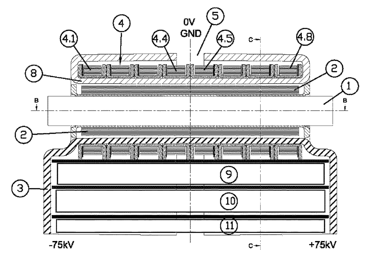
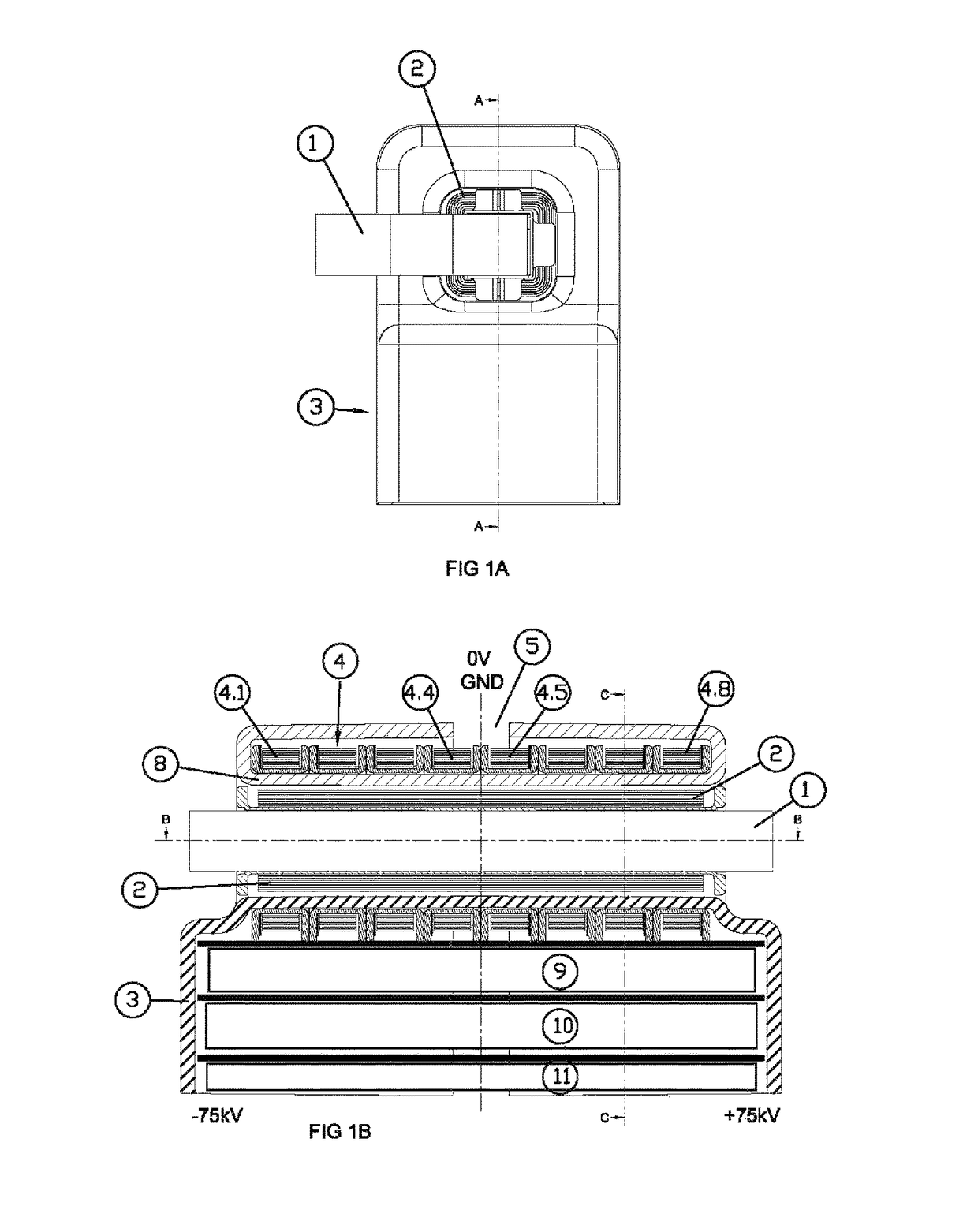
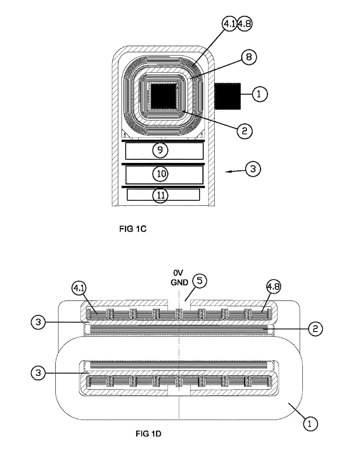
[0010]The object of the present invention is a high-voltage, high-frequency and high-power transformer in a very small space, which can be adapted to the dimensions of an X-ray tube, so that it can be assembled in a single module, so that the electric potentials coincide between them (equipotential installation) in this way reducing the weight and volume of the assembly for the purpose of making it more economical and efficient.
[0016]The primary winding and the secondary winding longitudinally occupy the same space, which maximizes the magnetic coupling between the windings and therefore also minimizes the reactance between them, which allows maximization of power output.
[0018]The distance between the primary and the secondary winding is minimized by means of the hollow tubular element that separates both windings, enabling good magnetic coupling without loss of insulation.
[0019]The geometry of the outer housing of each half of the insulator makes it possible to form a slot situated at zero volts level where a high degree of insulation is not necessary and, however, allows the oil to come into contact with the secondary winding.

Problems solved by technology

However, designing and building a transformer that includes these three characteristics simultaneously represents an enormous challenge, due to the conflicting requirements of each of the aforementioned characteristics.
This separation between windings reduces the magnetic coupling between the two and therefore leakage reactance increases, limiting the power output.

Method used


Image

  • High-voltage, high-frequency and high-power transformer
  • High-voltage, high-frequency and high-power transformer
  • High-voltage, high-frequency and high-power transformer

Examples


Embodiment Construction

[0010]The object of the present invention is a high-voltage, high-frequency and high-power transformer in a very small space, which can be adapted to the dimensions of an X-ray tube, so that it can be assembled in a single module, so that the electric potentials coincide between them (equipotential installation) in this way reducing the weight and volume of the assembly for the purpose of making it more economical and efficient.

[0011]The transformer is immersed in oil (mineral or vegetable), which has two main objectives: to serve as an electrical insulator and as a coolant for the transformer's electrical and magnetic elements.

[0012]The transformer has a core on which the primary winding is mounted, whereupon this assembly is housed inside a hollow tubular element which forms part of an insulator.

[0013]The insulator is made up of two parts which are symmetrical with respect to a transverse vertical plane, each part or half having a hollow tubular element housed inside an outer hous...


PUM

PropertyMeasurementUnit
low-voltage insulationaaaaaaaaaa
voltageaaaaaaaaaa
voltageaaaaaaaaaa

Abstract

High-voltage, high-frequency and high-power transformer having a core (1) on which a primary winding (2) is disposed on which a secondary winding (4) is disposed in an insulated manner, whereupon the entire assembly is housed and mounted in an insulator (3), wherein the insulator (3) is made up of two parts or halves (6) and (7) symmetrical with respect to a transverse vertical plane, each part having a hollow tubular element (3.1) housed inside an outer housing (3.2) of each half of the insulator, defining in each part an annular space (3.3) comprised between the outer wall of the tubular element (3.1) and the inner wall of the outer housing (3.2), where the secondary or high-voltage winding is disposed, the insulator (3) presenting in its outer housing (3.2) a slot (5), which is situated at zero volts level, and though which the oil penetrates towards the secondary winding.

Description

CROSS REFERENCE TO RELATED APPLICATION[0001]This application claims the benefit of PCT International Application Serial No. PCT / ES2014 / 070058 filed on Jan. 28, 2014 and entitled a “High-Voltage, High-Frequency and High-Power Transformer”, the entire disclosure of which is incorporated herein by reference.OBJECT OF THE INVENTION[0002]The object of the present invention, as established in the title, is a high-voltage, high-frequency and high-power transformer.[0003]The present invention is characterized by the special constructive characteristics of the insulator in particular, on which the core, the primary winding and the secondary winding are mounted, so as to achieve sufficient insulation between both windings, maximum magnetic coupling and the possibility of cooling the primary and secondary windings using oil, obtaining a transformer which can be adapted to the dimensions of an X-ray tube in a very small space.[0004]Therefore, the present invention relates to the field of transf...

Claims


Application Information

Patent Timeline
Patent Type & Authority Patents(United States)
IPC IPC(8): H01F27/02H01F27/32H01F27/24H01F27/12H05G1/08H01F27/28H05G1/06H01F5/02
CPCH01F27/2823H01F27/02H01F27/12H01F27/324H05G1/08H01F27/24H05G1/06H01F2005/025H01F27/325H01F27/32H01F19/00
Inventor MORENO VALLEJO, ILDEFONSODIAZ CARMENA, FRANCISCODIAZ CARMENA, ANGEL
Owner SOC ESPANOLA DE ELECTROMEDICINA & CALIDAD
Learn More