
Mobile variable power system and method

a power system and variable technology, applied in the direction of electric energy management, climate sustainability, driver interaction, etc., can solve the problems of power diminishing as the voltage of the onboard battery drops, power and effectiveness of the device is negatively affected, etc., to achieve efficient overall system function, less amperage, and high voltage

Active Publication Date: 2018-02-06
JOHNSEN STEPHEN G +3
View PDF14 Cites 41 Cited by
  • Summary
  • Abstract
  • Description
  • Claims
  • Application Information

AI Technical Summary

Benefits of technology

[0021]As discussed above, the higher the voltage in an electric vehicle, the less amperage is required and the more efficient the overall systems function. This is due to a basic electrical principle of Ohm's Law which states that V*I=P, which means voltage multiplied by amperage equals power. Additionally, a battery or cell will give out more energy and perform better the lower the amount of amperage that is being drawn from it. This holds true when there is a plurality of cells or batteries in an electric vehicle battery pack. Understandably, it would be advantageous to keep the electric vehicle's battery pack voltage as high as possible in order to keep the amperage demands lower, thereby improving performance and extending the useful range of the electric vehicle.
[0022]Electric vehicle users notice better performance and the ability to get the same performance while depressing the electric vehicle's accelerator pedal assembly less deeply when the electric vehicle has a full charge and especially when the electric vehicle has just been fully charged and the system voltage is at its highest. Understandably it would be advantageous to be able to always have the electric vehicle's battery pack and systems being charged and at as high a voltage as safely acceptable. This is akin to the easily recognizable power advantages of a constantly powered corded electric hand drill versus the diminishing power of a battery powered electric hand drill. The heavier the load on the battery powered drill, or the longer it has been used, the lower the voltage drops and thus the power and effectiveness of the device is negatively affected.
[0023]It is not practical to drive an electric vehicle only as far as an extension cord would allow and, accordingly, the result is that the power diminishes as the onboard battery voltage drops. By adding a device on the special range extending apparatus that keeps supplying desirable high voltage to the host / tow electric vehicle, it is effectively the same as charging the host / tow electric vehicle's battery pack as it is being driven. By connecting the output from the trailer or onboard apparatus to the most positive and negative connections on the host / tow electric vehicle's battery pack, it has the effect of keeping the host / tow electric vehicle's battery pack at or near the fully charged level while also allowing for the host / tow electric vehicle's battery pack to provide additional power in conjunction with the trailer or onboard apparatus, which can be useful for high power operations such as passing, accelerating or going up steep hills.

Problems solved by technology

The heavier the load on the battery powered drill, or the longer it has been used, the lower the voltage drops and thus the power and effectiveness of the device is negatively affected.
It is not practical to drive an electric vehicle only as far as an extension cord would allow and, accordingly, the result is that the power diminishes as the onboard battery voltage drops.

Method used


Image

  • Mobile variable power system and method
  • Mobile variable power system and method
  • Mobile variable power system and method

Examples


Embodiment Construction

[0038]It should be made clear at this point that whenever the words “Electric Vehicle” or “EV” are used in this document, they can refer to any vehicle with some means of electric propulsion. Vehicle as used herein includes manned and unmanned machines, crafts, and vehicles used in the air, on the land, or on the water, included submerged vehicles. This includes but is not limited to hybrid automobiles or trucks, fuel cell vehicles, pure battery electric vehicles and even diesel-electric or fully electric watercraft, buses, flying machines, and railed or rail riding or track guided vehicles such as trains, monorails, and magnetic levitation vehicles. The fundamental electric principles apply to all devices and systems with an electric component.

Apparatus Mobilization Methods:

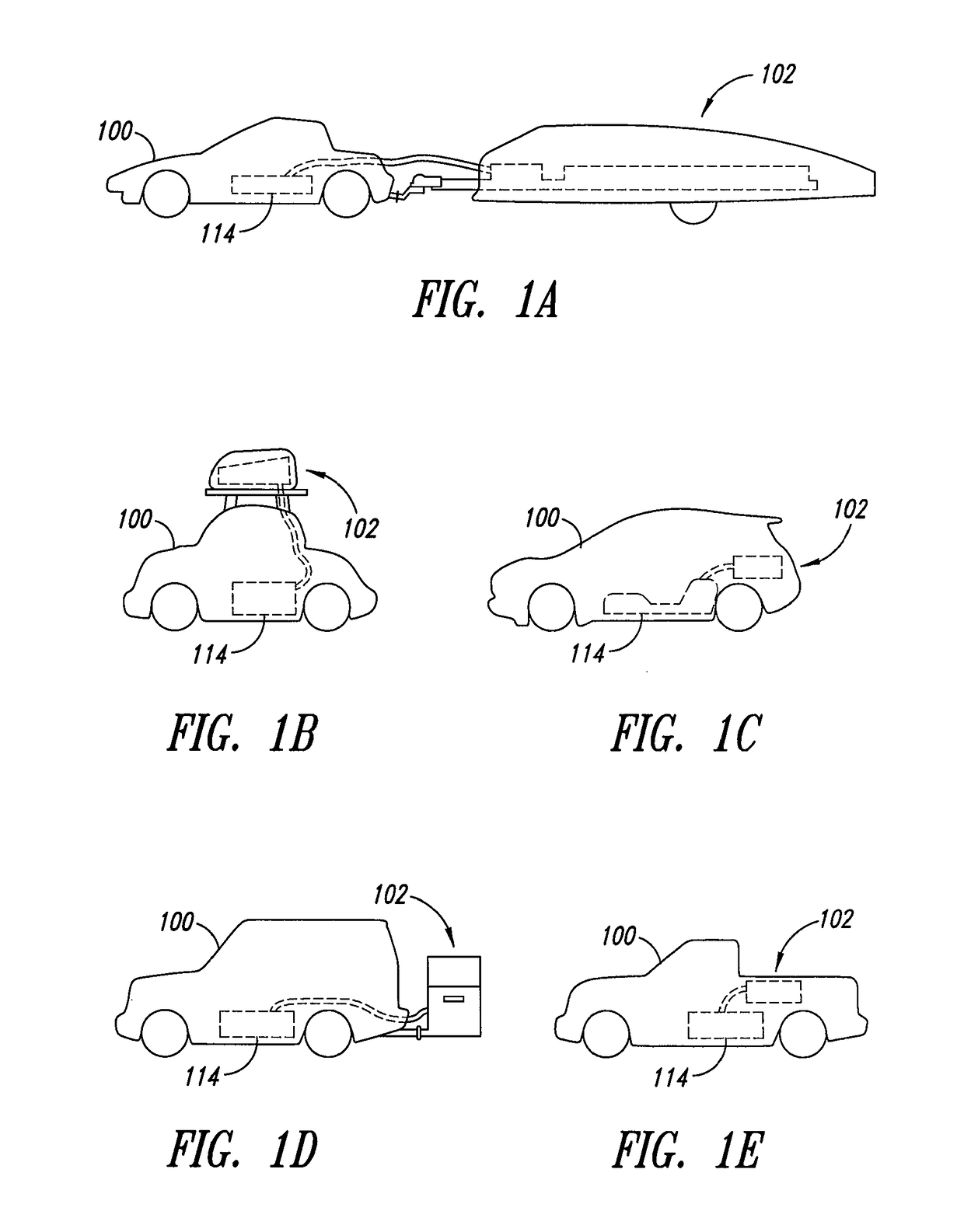
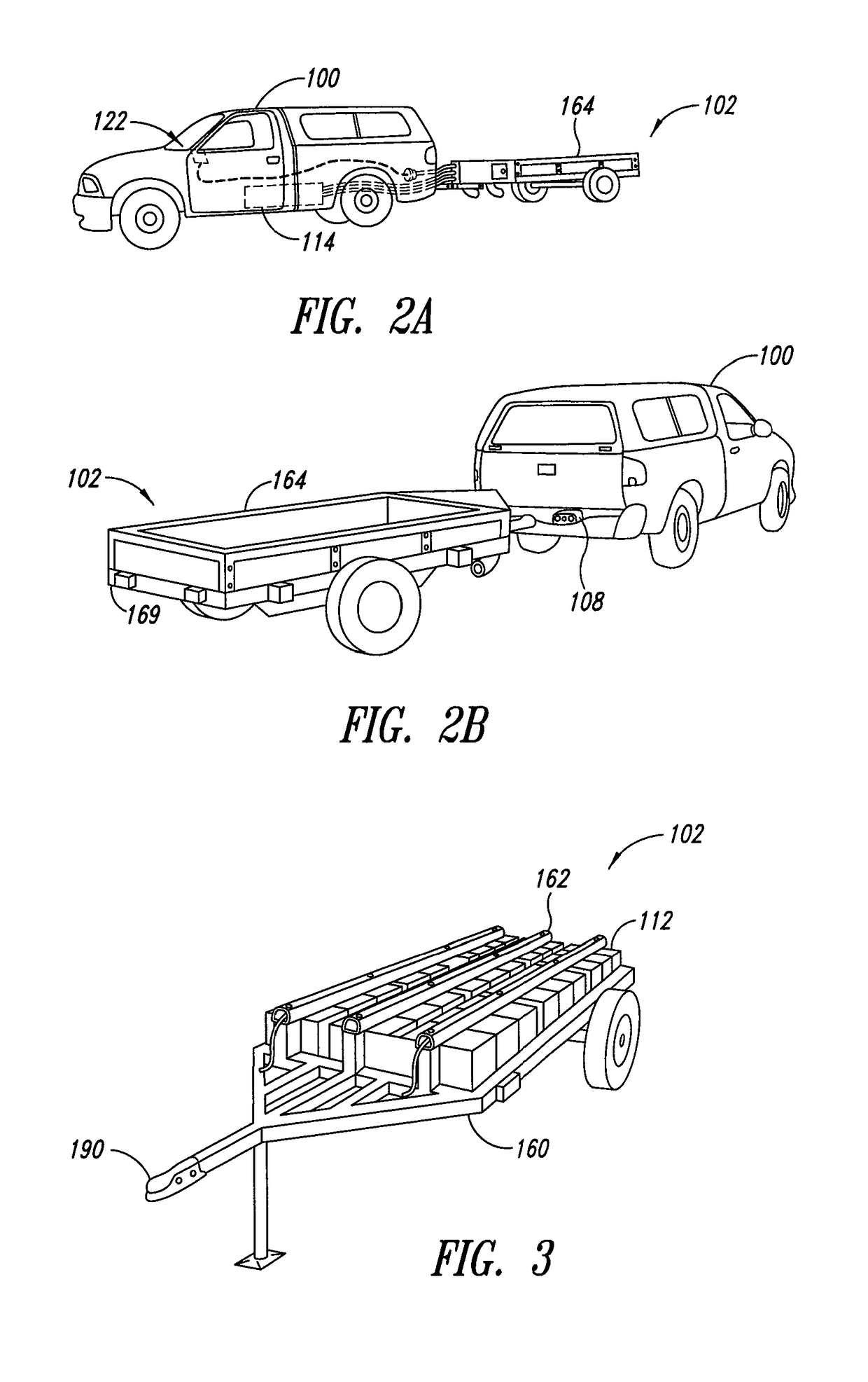
[0039]FIGS. 1A through 1E and FIGS. 2A through 2B show several embodiments of mobile transportation, such as a motor vehicle 100, using a mobile energy storage apparatus 102 formed in accordance with the present...


PUM


Abstract

A mobile energy storage apparatus comprised of: a. at least one variable energy control device which converts DC to DC, AC to DC and DC to AC and b. at least one energy storage device (such as a battery) and c. a means to adjust said at least one variable energy control device to various electrical output powers and d. a means to connect said mobile energy storage apparatus to an EV (electric vehicle) or other device electrically and mechanically to enable transferring energy even when in motion and e. optionally a means for attaching various covers to said mobile energy storage apparatus to suit various applications. The mobile energy storage apparatus allows the transfer of energy to or from: an EV, a building or any other electrical facility or device and can be configured with built-in or attached to various power sources.

Description

BACKGROUND[0001]Technical Field[0002]The present disclosure pertains to apparatus, systems and methods for providing power to electric vehicles and other electrical objects or systems using a mobile energy storage apparatus that has variable power inputs and outputs.[0003]Description of the Related Art[0004]At the time of this writing, the combustion engine is the most common form of propulsion for land vehicles, water craft, and aircraft. The most common combustion engines are fueled by petroleum or other fossil fuels, which are in limited supply on this planet. It would be advantageous to have a flexible solution for propulsion that does not rely on one energy source.[0005]Electricity is an option and there are many methods of producing it. Whereas combustion fuels rely on limited supply or limited land area to grow fuel, electricity generation has a number of sources including but not limited to: wind, solar, tidal, wave, geothermal, nuclear, coal, natural gas, diesel, gasoline, ...

Claims


Application Information

Patent Timeline
Patent Type & Authority Patents(United States)
IPC IPC(8): H02J7/14B60L11/00H02J7/00B60L11/16B60L11/18B60L1/00B60L50/30
CPCH02J7/0065B60L11/005B60L11/16B60L11/1816B60L11/1824B60L11/1864B60L11/1877B60L11/1879B60L11/1896H02J7/0054H02J7/0055B60L1/006Y02T90/34B60L2200/10B60L2200/12B60L2200/26B60L2200/28B60L2200/30B60L2200/32B60L2200/36B60L2210/10B60L2210/40B60L2230/16B60L2230/24B60L2230/30B60L2250/16B60L2260/22B60L2260/32H02J7/0042H02J2007/0067Y02T10/7022Y02T10/7061Y02T10/7088Y02T10/7216Y02T10/7241Y02T90/121Y02T90/127Y02T90/128Y02T90/14Y02T90/163B60L53/14B60L50/40B60L50/30B60L58/19B60L58/21B60L50/66B60L50/64B60L50/71B60L53/305B60L53/51B60L53/52B60L53/53H02J2207/40H02J7/342B60L53/68H02J2310/48Y02T10/70Y02T10/7072Y02T10/72Y02T90/12Y02T90/16Y02T90/40H02J2207/20B60L53/30
Inventor JOHNSEN, STEPHEN G.EASLEY, RONALD L.JOHNSEN, KENNETH G.HOHN, CHAD M.
Owner JOHNSEN STEPHEN G
Learn More