Floating structure and method for obtaining same

a technology of floating structure and beam, which is applied in the field of floating structure, can solve the problems of beam cracking and breaking, floating stability problems, and no final result has been achieved, and achieves the effects of increasing resistance and floatability, preventing overturning, and improving operating efficiency

Active Publication Date: 2018-02-27
ESPANOLA DE PLATAFORMAS MARINAS SL
View PDF29 Cites 2 Cited by
  • Summary
  • Abstract
  • Description
  • Claims
  • Application Information

AI Technical Summary

Benefits of technology

[0004]Consequently, a new floating structure has been designed to be enhanced as, for example, a platform for supporting or transporting people or goods, or for breeding several sea species, which is capable of reducing or eliminating all mentioned issues, thus increasing resistance and floatability, with or without load, also preventing overturning, thus improving operating efficiency and extending its useful life, as well as providing a simple, economical method for obtaining it.DESCRIPTION OF THE INVENTION
[0006]The structure is expected to be built with beams made of stable materials for outdoor use, such as high-density polyethylene, even though the use of other plastic polymers, metals or metal alloys cannot be discarded. Thus, beams in the structure are provided according to a first plurality of members and a second plurality of members; each member may be of a synthetic plastic material or any other material with high stability for outdoor use, such as stainless steel, although any of them can be used for building the structure. For temporary connections, welding is preferred to join the beams or the grid elements not only because it is easier and more economical than any other alternative processes, but also because the pieces that are so joined become a single one that is as strong or even stronger than the individual elements if the filling material endurance properties to be contributed are strong, which guarantees multiple solutions.
[0009]Both inserting the tubes of the second plurality into those of the first plurality and welding the connecting part of the former into the latter lock the system, dissipate the vibrations of the waves on the structure and prevent the concentration of rupture stress at the connecting points between tubes.
[0018]It is evident, according to what has been said, that the structure is to be supplemented for use, for example, as a farming platform by closing part of the tubes, or all of them making up the beams of the structure, through hydrodynamic or other closing device at the ends, and / or by partitioning all or part of the tubes, and even providing the structure with a system of valves to select when to pour water into and out of the resulting compartments, so that the structure can be used underwater. It is also evident that the structure is to be supplemented for further use with bars or other supports for the breeding ropes, or with braces or supports for the cages and the breeding nets it shall carry, or with walkways for workers, anchoring side reinforcements, control means, direction means, stabilizers, levellers and / or signalling sets or other typical elements of this type of platforms. Under certain conditions, and, in order to minimise the possible effects of environmental exposure, it could be convenient to provide the structure surfaces with protective coating, such as stable paint or similar.

Problems solved by technology

In either model, the culture weight puts the beams under big deflective efforts, causing tensile and compressive strains, which in turn leads to shear strengths on the supports as well as torsion strains, which causes floating and stability problems, and beam cracking and breaking, usually due to deterioration of the building materials and the connections between them.
On the other hand, several tests have been performed for improving the design or materials of the connections; however, no result has yet been final.
These building contributions have proved to be inefficient, as they must be continuously adjusted and the materials used usually tear open.

Method used


Image

  • Floating structure and method for obtaining same
  • Floating structure and method for obtaining same
  • Floating structure and method for obtaining same

Examples


Embodiment Construction

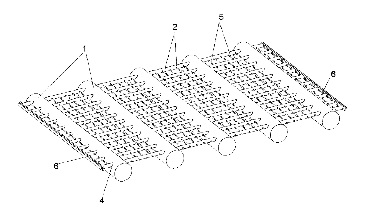
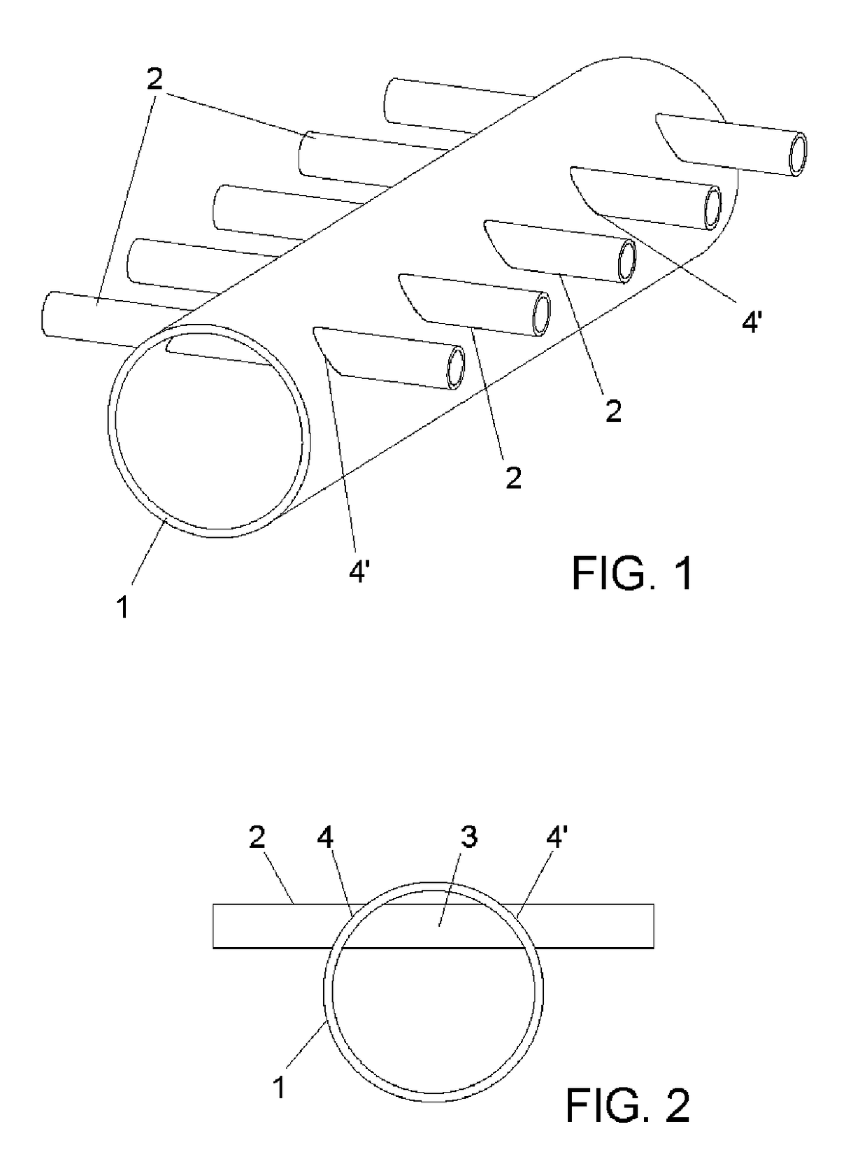
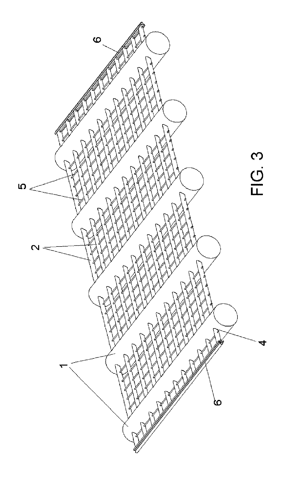
[0005]As expressed in the corresponding paragraph of these specifications, the invention relates to a floating structure used in aquaculture, which significantly Improves the ones in use now; such enhancements affect the connections between grid elements and, therefore, the floating system when the structure is in use.

[0006]The structure is expected to be built with beams made of stable materials for outdoor use, such as high-density polyethylene, even though the use of other plastic polymers, metals or metal alloys cannot be discarded. Thus, beams in the structure are provided according to a first plurality of members and a second plurality of members; each member may be of a synthetic plastic material or any other material with high stability for outdoor use, such as stainless steel, although any of them can be used for building the structure. For temporary connections, welding is preferred to join the beams or the grid elements not only because it is easier and more economical th...


PUM

PropertyMeasurementUnit
diameteraaaaaaaaaa
diameteraaaaaaaaaa
diameteraaaaaaaaaa

Abstract

A floating structure and method for obtaining same. The structure includes a first plurality of tubes and a second plurality of tubes. The second plurality of tubes are inserted into the first plurality of tubes to extend through the upper portion of same, and both sets of tubes are welded together. The ends of the tubes of the first plurality of tubes are closed in order to be used as flotation tanks when the floating structure is fitted out for such use. The method concerns locking the first plurality of tubes in place on the frame, with pairs of holes in each of the first plurality of tubes being aligned, and a corresponding tube of the second plurality of tubes being inserted through each pair of aligned holes by force. Each of the connection portions or parts contained in the tubes are welded on the periphery of the holes.

Description

TECHNICAL ASPECTS[0001]The invention relates to a floating structure and to a method for building it. In particular, this invention refers to a floating structure to be used in aquatic environments as support or transport structure, as well as a sea platform for farming aquatic species and to a method for obtaining same. The structure can be used as a stand-alone element, or as a module, to be part of a floating platform or a platform that can be sunk to buffer sea beating so as to preserve culture and be raised to surface to collect culture.BACKGROUND OF THE INVENTION[0002]There are floating structures made up of a grid of large beams and large floaters for goods support and transportation; some of them have added nets or cages where the sea species are kept to breed. There are other grids with ropes that are set perpendicular to it and sink in the water, some sea species, such as bivalve shellfish, mussels or oysters, stick to them to breed. In either model, the culture weight put...

Claims


Application Information

Patent Timeline
Patent Type & Authority Patents(United States)
IPC IPC(8): B63B38/00A01K61/54A01K61/00B63B3/04A01K61/60
CPCB63B38/00A01K61/00A01K61/60B63B3/04A01K61/54Y10T29/49826B63B35/00A01K61/55B63B2035/4493B63B35/613Y02A40/81
Inventor QUINTA CORTINAS, ANDRES
Owner ESPANOLA DE PLATAFORMAS MARINAS SL
Why Eureka
Try Eureka