Supercharge Your Innovation With Domain-Expert AI Agents!

Segmented variable-configuration radio antenna

a radio antenna and variable configuration technology, applied in the field of radio communication, can solve problems such as difficult or impossible conversion, and achieve the effects of high efficiency, fast and easy attachment or disassembly, and quick connection/disassembly

Inactive Publication Date: 2018-03-06
FERREIRA DAVID HENRY
View PDF1 Cites 0 Cited by
  • Summary
  • Abstract
  • Description
  • Claims
  • Application Information

AI Technical Summary

Benefits of technology

The present invention introduces a novel antenna construction technique that can be utilized in various existing antenna designs. It allows for quick and easy adjustment of the antenna length to cover a wide range of frequencies, without the need for expensive and heavy fixed-length antennas. The technique also enables quick reconfiguration of the feed-point location, making it ideal for various applications such as stealth and speed. Overall, this invention offers a lightweight, cost-effective, and convenient solution for altering the performance of antennas.

Problems solved by technology

This quickly and easily converts the antenna from a balanced dipole to an end-fed dipole—a conversion which is difficult or impossible when using fixed-length wire, wire with traps or telescopic antennas.

Method used


Image

  • Segmented variable-configuration radio antenna
  • Segmented variable-configuration radio antenna
  • Segmented variable-configuration radio antenna

Examples


example 1

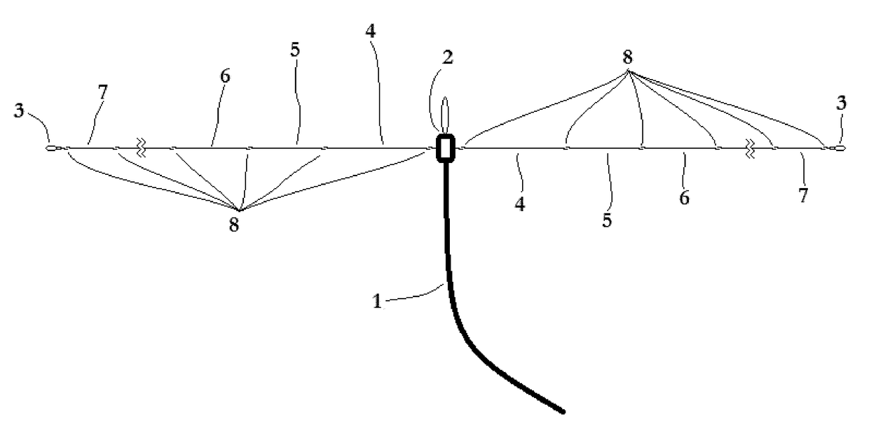
[0034]A user who is communicating on 10 meter band using segment “A”, may switch to 15 meter band simply by snapping in place one or more additional wire segments (segment “B”) onto the end of their antenna. This additional segment would be trimmed such that, when combined with segment “A”, the overall antenna length is optimal for 15 meter band frequencies.

example 2

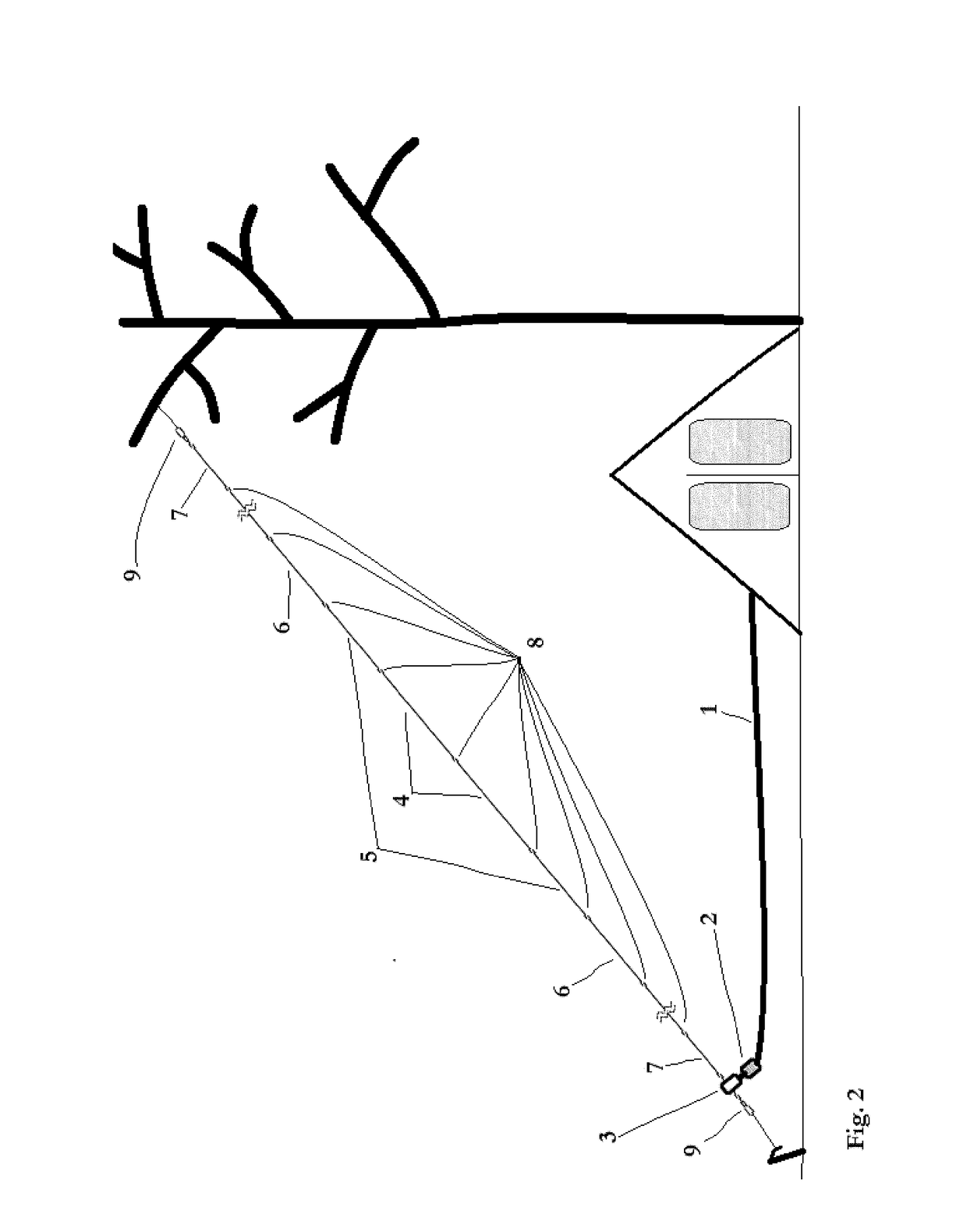
[0035]A user is hiking / camping cross-country. At site A, they are camped among tall trees and user has his antenna configured as center-fed with segments in place for efficiency on the 20 meter band. The next day, user hikes 10 miles to a site where there is only 1 tree and no other tall structures. User unsnaps his feed point from the middle of the antenna and snaps together the two polar segments of the antenna. She then quickly snaps her feed point onto the one end of the antenna and snaps a terminal connector (non-element, rope loop for hanging) on to the other feed point connector. User throws a weighted pilot string high up tree, connects rope and other terminal connector to other end of antenna and pulls one end of antenna high up into tree. The lower end of antenna is connected (insulated or not) to a spike in ground away from the tree. The result is a sloping end-fed dipole antenna.

[0036]In FIG. 1, there is shown the convertible antenna in a center-fed dipole configuration ...


PUM


Abstract

A segmented radio antenna that uses electrically conductive quick connect / disconnect devices between segments to accomplish a conversion from efficiency on one band to efficiency on another band AND / OR to convert quickly and easy between center-fed and end-fed (or a variety of feed-point configurations).The innovative use of flexible wire segments and connectors reduces the overall weight and cost of the antenna when compared to the use of traps or telescoping antennas.

Description

BACKGROUND OF THE INVENTION[0001]The present invention is in the technical field of radio communications. More particularly, the present invention is in the technical field of antenna design.[0002]A dipole antenna is the simplest form of radio antenna. It consists of two electrically-conductive elements positioned such that passing radio waves cause a voltage differential between the two elements.[0003]In the case of radio signal reception, this voltage differential, however small, is passed through a feed line to a radio frequency (RF) receiver where it is converted into audio, video, text or other content.[0004]In the case of transmission, an oscillating voltage differential is generated by a radio transmitter and passed to the antenna by way of a feed line, creating radio waves in space.[0005]Dipole antennas may be “balanced”, having two elements of equal lengths with a feed point in the center. Or they may be “end-fed” with one element making up nearly the entire length of the a...

Claims


Application Information

Patent Timeline
Patent Type & Authority Patents(United States)
IPC IPC(8): H01Q9/20H01Q1/08H01Q9/16H01Q1/14H01Q21/30
CPCH01Q9/20H01Q1/088H01Q21/30H01Q9/16H01Q1/14
Inventor FERREIRA, DAVID HENRY
Owner FERREIRA DAVID HENRY
Features
  • R&D
  • Intellectual Property
  • Life Sciences
  • Materials
  • Tech Scout
  • Unparalleled Data Quality
  • Higher Quality Content
  • 60% Fewer Hallucinations
Learn More