Particle production apparatus

a technology of particle production and straightening device, which is applied in the direction of wire straightening device, manufacturing tools, transportation and packaging, etc., can solve the problems of reduced minimum ignition energy of particles, reduced production efficiency, and relatively high manufacturing cost of chemical approaches, so as to improve the productivity and safety of mass production

Active Publication Date: 2018-03-13
METAL INDS RES & DEV CENT
View PDF12 Cites 0 Cited by
  • Summary
  • Abstract
  • Description
  • Claims
  • Application Information

AI Technical Summary

Benefits of technology

[0008]Accordingly, the invention is directed to a straightening device and a particle production apparatus using the same, in which a metal wire is continuously input to a generating device to continuously generate particles, and the generated particles are distributed in a dense medium, so as to greatly improve productivity and safety of a mass production.
[0010]The invention provides a straightening device, which is adapted to straighten a metal wire. The straightening device includes a stage, an ultrasonic source and a pressure head. The metal wire is driven to pass through the stage and is carried by the stage. The pressure head covering the stage is connected to the ultrasonic source, such that an ultrasonic wave is exerted to the metal wire passing through the stage to eliminate an internal stress of the metal wire, so as to straighten the metal wire along a straight-line direction.
[0011]According to the above description, the straightening device and the particle production apparatus of the invention may control a length of the metal wire and straighten the same to effectively control a particle size of the particles generated during continuous electric explosion of the metal wire.
[0012]In other words, based on arrangement of a shifting device and the conveying device, the length of the metal wire between the first electrical conducting element and the second electrical conducting element may reach the predetermined length, which represents that the particle production apparatus is able to maintain consistency of the length of the metal wire in each electric explosion process, and meanwhile the straightening device may effectively eliminate the internal stress of the metal wire and maintain the shape of the metal wire along a fixed direction for contacting the electric conducting elements, so as to avoid a bending status of the metal wire when the metal wire contacts the electrical conducting elements to influence the quality of the particles obtained through the electric explosion.
[0013]Moreover, when a surface contour of the electrical conducting elements is changed due to the previous explosion, the shifting device may adjust a distance between the electrical conducting elements to effectively maintain consistency of the length of the metal wire between the electrical conducting elements.

Problems solved by technology

Some practitioners produce the nanoparticles by using a chemical approach, during a manufacturing process adopting the chemical approach, since a chemical activity of the nanoparticles is required to adopt a proper reactant, besides some precious metals, the chemical approach is not suitable for producing general metal nanoparticles, and the manufacturing cost of the chemical approach is relatively high, and particle size distribution is relatively wide range.
However, the metal vapour synthesis method has to be implemented under a vacuum environment, which is subjected to considerable restrictions in an actual production application.
However, although the particle sizes of the nanoparticles produced according to the above grinding method are relatively small, during the manufacturing process, the smaller the particle size of the produced particles is, the more easier the particles float in the air to form nano dust, and the minimum ignition energy of the particles becomes smaller, such that the nano dust is easy to be ignited.
Regarding a titanium powder and an iron powder with the particle size of a nano scale, the minimum ignition energy thereof is smaller than 1 mJ, and during the manufacturing process, due to the factors of static electricity, impact or open flame, it is extremely easy to cause combustion and explosion, which causes many crises of fires and explosions during the process of manufacturing the nanoparticles.

Method used


Image

  • Particle production apparatus
  • Particle production apparatus
  • Particle production apparatus

Examples


Embodiment Construction

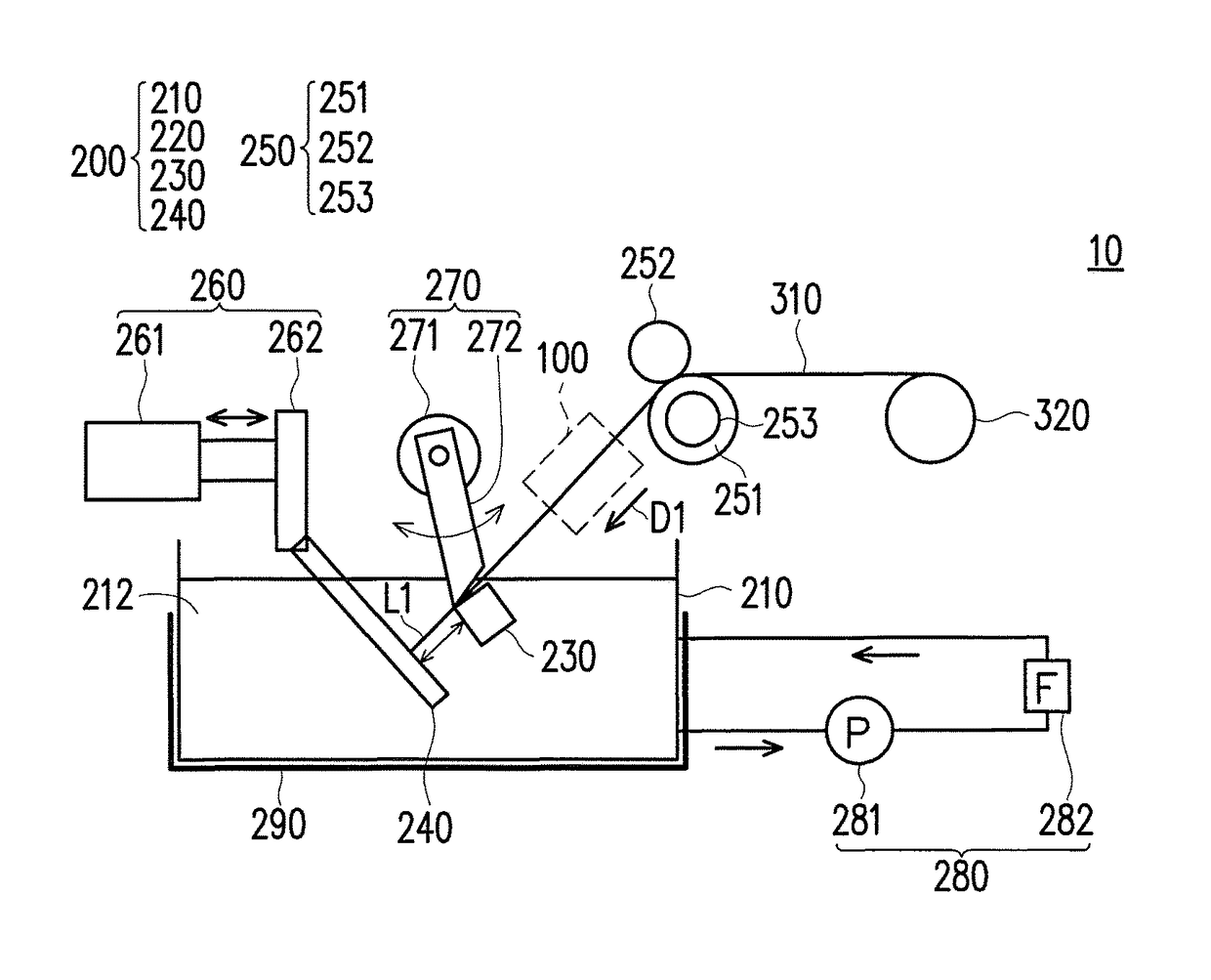
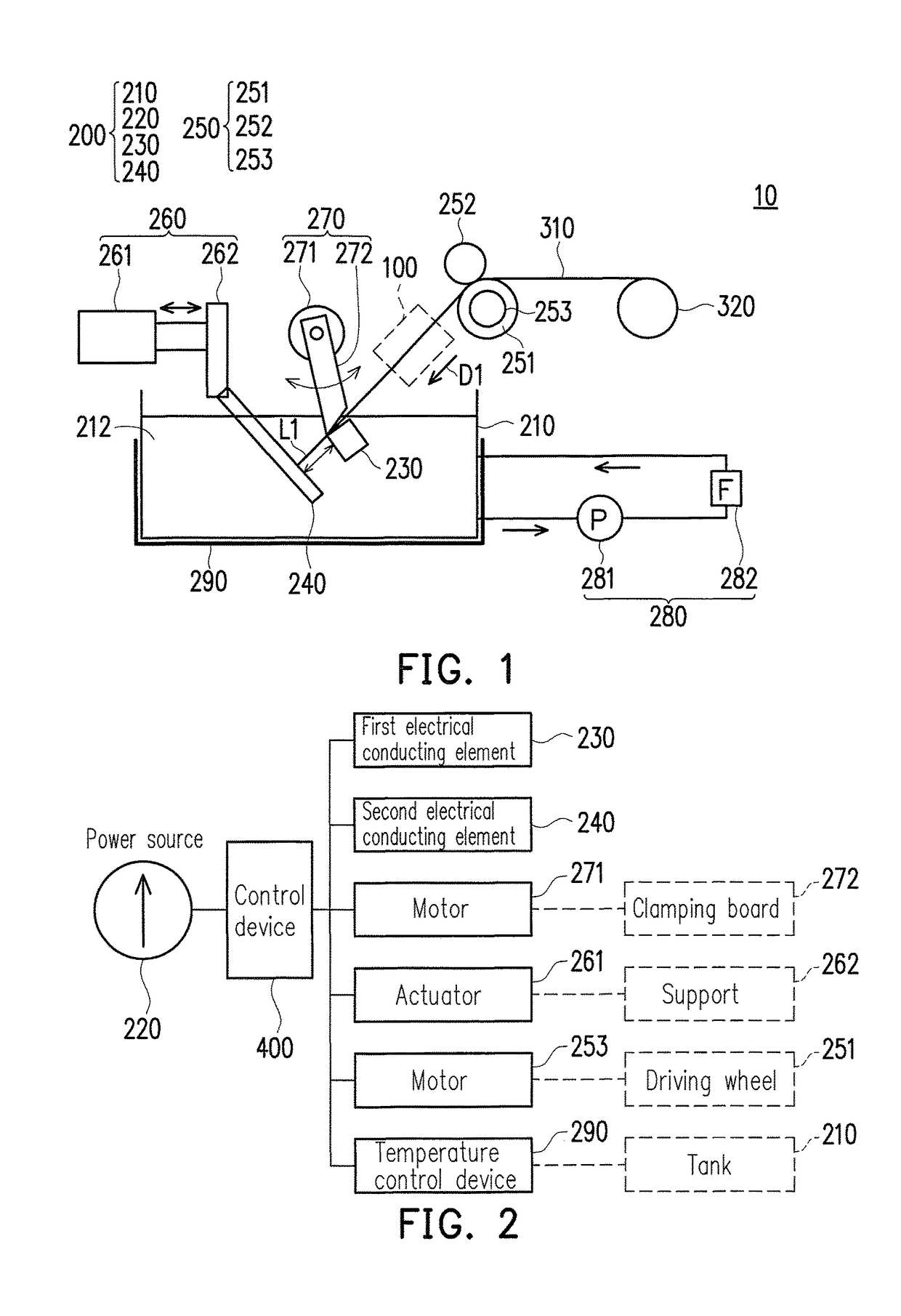
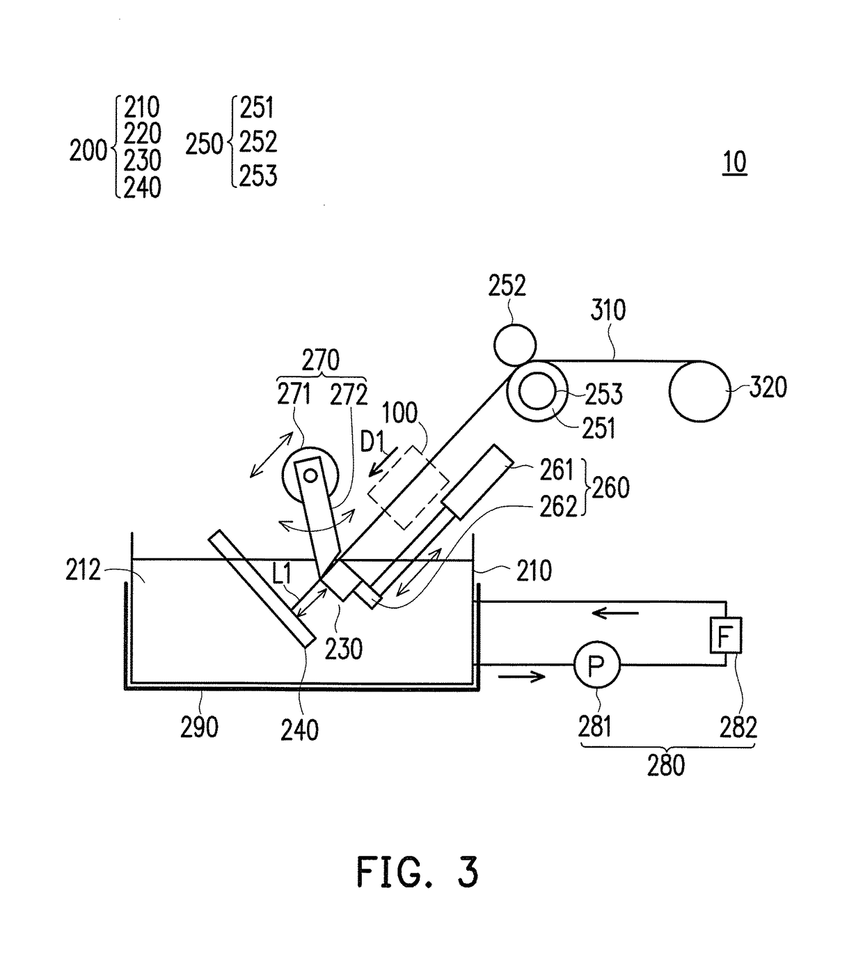
[0024]FIG. 1 is a schematic diagram of a particle production apparatus according to an embodiment of the invention. FIG. 2 is a schematic diagram illustrating electrical connections of related components of FIG. 1. Referring to FIG. 1 and FIG. 2, in the present embodiment, the particle production apparatus 10 includes a generating device 200, a conveying device 250, a control device 400, a straightening device 100 and a shifting device 260. The generating device 200 includes a tank 210, an electric power source 220, a first electrical conducting element 230 and a second electrical conducting element 240. The tank 210 is filled with a dense medium 212 in a liquid state, and the first electrical conducting element 230 and the second electrical conducting element 240 are disposed in the dense medium 212 and are electrically connected to an anode and a cathode of the electric power source 220, respectively, and the control device 400 is electrically connected thereto for controlling a r...


PUM

PropertyMeasurementUnit
voltageaaaaaaaaaa
voltageaaaaaaaaaa
diameteraaaaaaaaaa

Abstract

A particle production apparatus including a generating device, a conveying device, and a straightening device is provided. The generating device includes a tank filled with a dense medium, an electric power source, a first and a second electrical conducting element received in the dense medium and coupled to an anode and a cathode of the electric power source respectively. The conveying device is configured to convey a metal wire into the tank and make the metal wire to contact the first electrical conducting element and the second electrical conducting element in a straight-line direction, so as to produce an electric explosion to form a plurality of particles in the dense medium.

Description

CROSS-REFERENCE TO RELATED APPLICATION[0001]This application claims the priority benefit of Taiwan application serial no. 104131452, filed on Sep. 23, 2015. The entirety of the above-mentioned patent application is hereby incorporated by reference herein and made a part of this specification.BACKGROUND OF THE INVENTION[0002]Field of the Invention[0003]The invention relates to a straightening device and a particle production apparatus using the same.[0004]Description of Related Art[0005]Along with the continuous development of an application field of nanopowder, demand on quantity of nanoparticles has continuously increased, and in order to satisfy the demand of the nanoparticles, related practitioners devote to research and develop a mass production technique and an apparatus capable of improving productivity of the nanopowder while considering a property of the nanoparticles and production safety thereof.[0006]Some practitioners produce the nanoparticles by using a chemical approac...

Claims


Application Information

Patent Timeline
Patent Type & Authority Patents(United States)
IPC IPC(8): B22F9/14B21F1/02B21C19/00B22F1/00B22F1/054
CPCB22F9/14B21C19/00B21F1/02B22F1/0018B22F2999/00B22F2203/03B22F2202/06B22F1/054B22F1/056
Inventor HSU, TAI-HSINCHUANG, YINCHIEN, WEN-PINCHANG, CHI-MINGFU, HO-CHUNGCHEN, CHANG-PEN
Owner METAL INDS RES & DEV CENT
Why Eureka
Try Eureka