
Scaffolding pipe of a structural scaffolding system and scaffolding element

a scaffolding system and scaffolding pipe technology, applied in the direction of building scaffolds, mechanical devices, building aids, etc., can solve the problems of less stable less convenient insertion of scaffolding pipes one into the other, and less stability of scaffolding systems, etc., to facilitate insertion of insertion portions, reduce the effect of radial play and reduce the risk of radial play

Active Publication Date: 2018-03-20
PERI GMBH
View PDF54 Cites 2 Cited by
  • Summary
  • Abstract
  • Description
  • Claims
  • Application Information

AI Technical Summary

Benefits of technology

The design ensures stable and load-bearing connections with minimal radial play, facilitating easy construction and disassembly of scaffolding systems while maintaining high stability and load-bearing capacity.

Problems solved by technology

However, this radial play is disadvantageous with respect to the stability of the scaffolding system since the upper scaffolding pipe can tilt readily relative to the lower scaffolding pipe.
However, this advantage comes at the expense of the disadvantage that the insertion of the scaffolding pipes one into the other is no longer so easily possible and the pipes become more readily jammed or tilted during the construction or disassembly of scaffolding, in particular when a scaffolding pipe of a frame element is inserted significantly before the other scaffolding pipe of the frame element.

Method used


Image

  • Scaffolding pipe of a structural scaffolding system and scaffolding element
  • Scaffolding pipe of a structural scaffolding system and scaffolding element
  • Scaffolding pipe of a structural scaffolding system and scaffolding element

Examples


Embodiment Construction

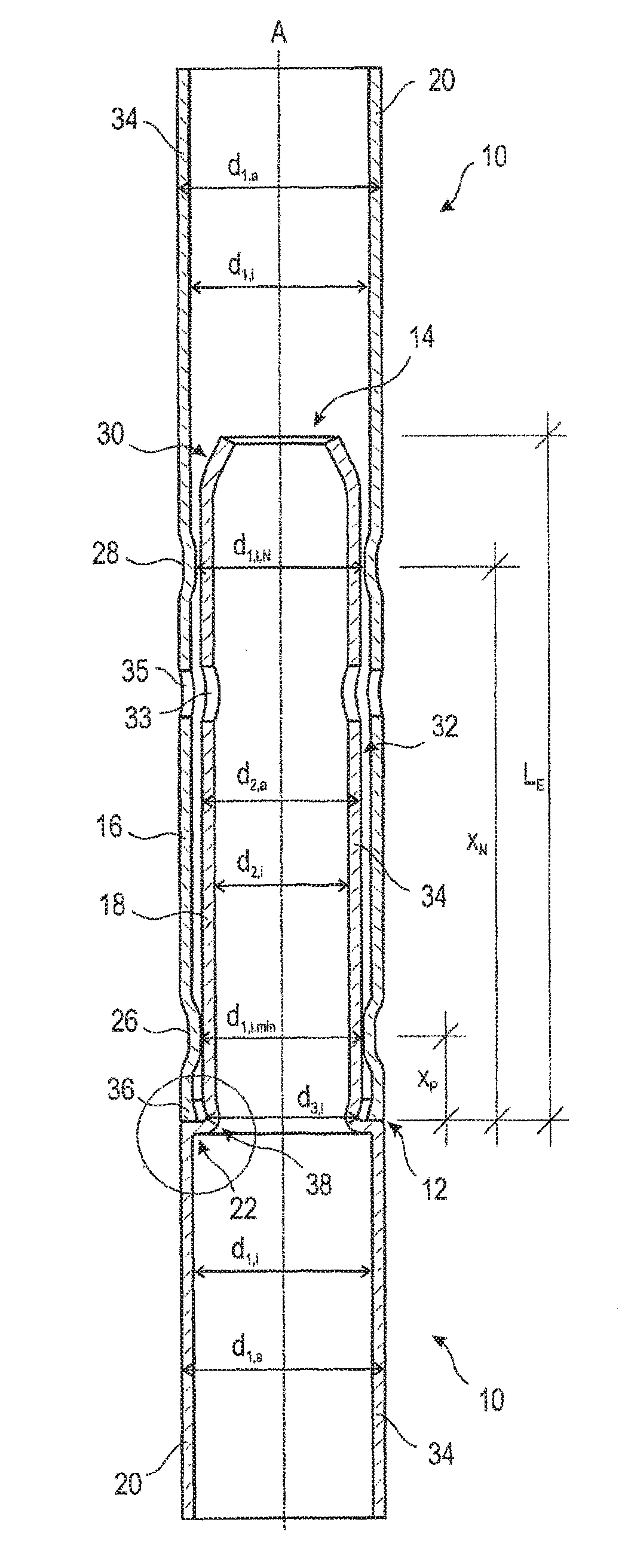
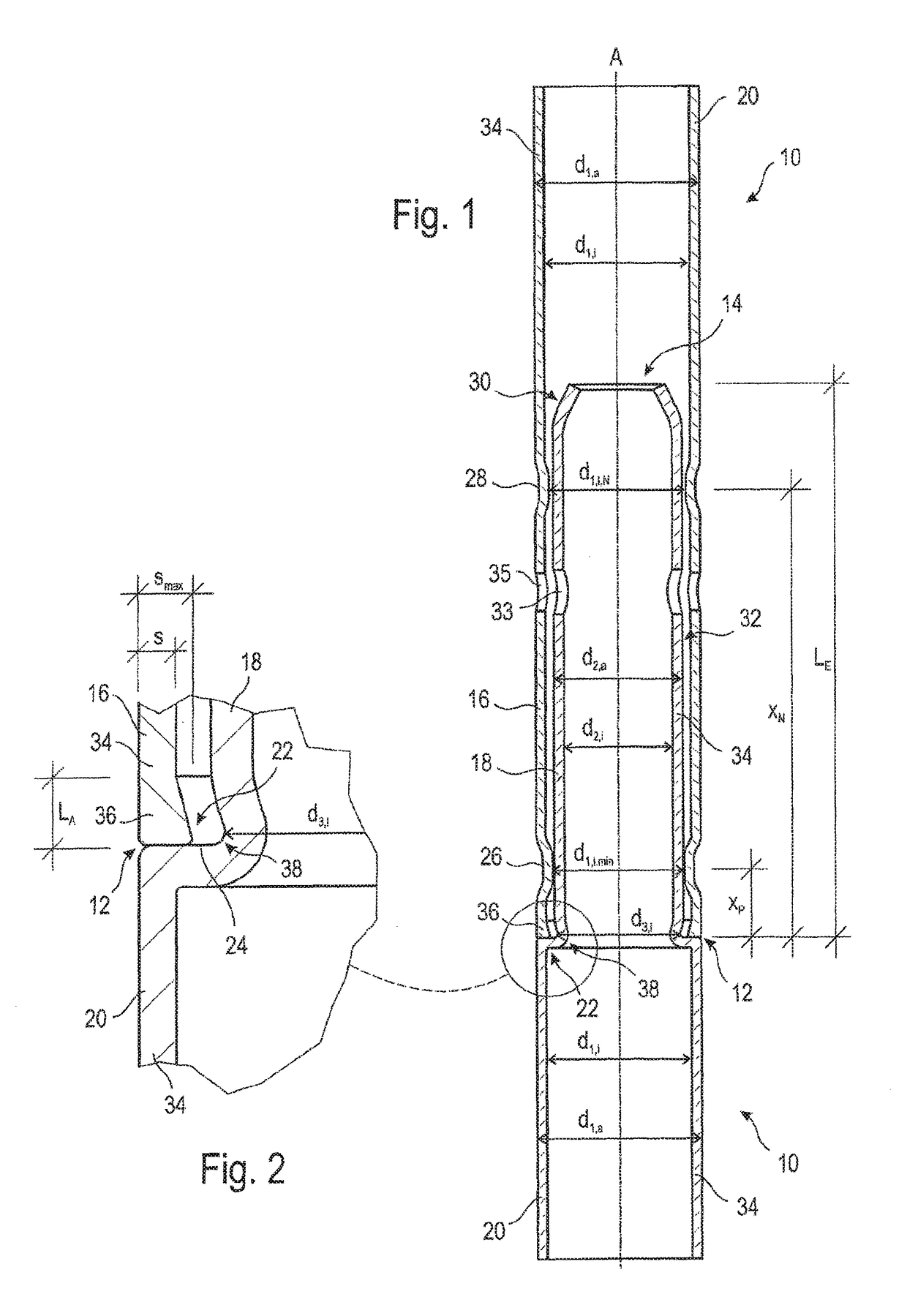
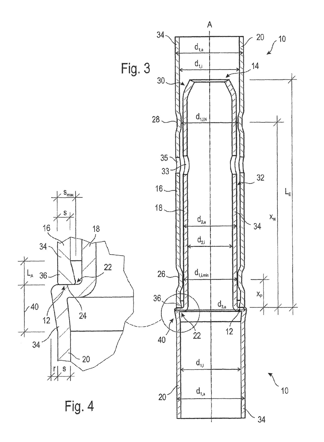
[0034]FIGS. 1 to 4 show scaffolding pipes 10 for a structural scaffolding system, which pipes may be constructed as rods or members of a scaffolding element, for example, a frame element which is shown later. Each scaffolding pipe 10 comprises a pipe axis A which extends from a first axial pipe end 12 to an opposed second axial pipe end 14, a receiving portion 16 which is provided on the first axial pipe end 12 and an insertion portion 18 which is provided on the second axial pipe end 14 and which has a smaller outer cross-section than the remaining portions of the scaffolding pipe 10.

[0035]An inner diameter d1,i of the receiving portion 16 is larger than an outer diameter d2,a of the insertion portion 18 so that an adjacent scaffolding pipe 10 having an identical insertion portion 18 can be inserted into the receiving portion 16.

[0036]An intermediate region 20 connects the receiving portion 16 to the insertion portion 18, the intermediate region 20 preferably merging in a stepless ...


PUM


Abstract

A scaffolding pipe of a structural scaffolding system extends from a first axial pipe end to an opposing second axial pipe end. A receiving portion is provided on the first axial pipe end and an insertion portion is provided on the second axial pipe end. The insertion portion has a reduced cross-section compared with the receiving portion and terminates with a radial shoulder which forms a support face. The receiving portion inner diameter is greater than the insertion portion outer diameter. The receiving portion at the first axial pipe end has one positioning groove which is interrupted or continuous in a peripheral direction which reduces the inner diameter of the receiving portion and which defines the minimum inner diameter of the receiving portion. A pipe wall of the scaffolding pipe has at the first axial pipe end a maximum wall thickness greater than the otherwise smaller wall thickness.

Description

CROSS-REFERENCE TO RELATED APPLICATIONS[0001]This continuation application claims priority to PCT / EP2014 / 065753 filed on Jul. 22, 2014 which has published as WO 2015 / 014676 A1 and also the German application number 10 2013 108 326.9 filed on Aug. 2, 2013, the entire contents of which are fully incorporated herein with these references.FIELD OF THE INVENTION[0002]The invention relates to a scaffolding pipe of a structural scaffolding system having a pipe axis which extends from a first axial pipe end to an opposing second axial pipe end, a receiving portion which is provided on the first axial pipe end and an insertion portion which is provided on the second axial pipe end and which has a reduced cross-section compared with the receiving portion and terminates with a radial shoulder which forms an annular support face which is directed towards the insertion portion, the inner diameter of the receiving portion being greater than the outer diameter of the insertion portion so that an a...

Claims


Application Information

Patent Timeline
Patent Type & Authority Patents(United States)
IPC IPC(8): F16L13/00E04G7/30E04G1/06E04G7/20E04G1/14F16L19/02F16L13/04F16L19/025F16L13/16
CPCE04G7/301E04G1/06E04G1/14E04G7/20F16L19/025F16L13/04F16L13/16F16L19/02E04G7/30
Inventor ERATH, FRANKLEDER, CHRISTIANSPECHT, RUDOLF
Owner PERI GMBH
Learn More