Surgical apparatus actuator

a technology for surgical instruments and actuators, which is applied in the field of surgical instruments, can solve the problems of aggravated wear to the mould punch, reduced mould life, and high cost of processing technology, and achieves the effects of improving the difficulty of nail groove molding, high accuracy, and providing nail grooves

Active Publication Date: 2018-03-27
EZISURG MEDICAL CO LTD
View PDF6 Cites 776 Cited by
  • Summary
  • Abstract
  • Description
  • Claims
  • Application Information

AI Technical Summary

Benefits of technology

[0022]In comparison with the existing technology, this invention has the following beneficial effects:
[0023]1. It mainly uses the nail anvil plate and nail anvil seat made of different materials to constitute the nail anvil assembly. As a result, the requirements of the nail anvil assembly for both material plasticity and bending strength are met. In which, the nail anvil plate uses thin stainless steel sheet for molding through tensile process to improve the difficulty in nail groove molding and provide nail grooves with a high accuracy; the nail anvil seat adopts a structural, material and processing proposal being able to provide a high bending strength to provide a strong bending property to the whole nail anvil assembly;
[0024]2. The tensile strength of the material used by the nail anvil seat is higher than that of the material used by the nail anvil plate, which enables the nail anvil seat to provide a higher tensile strength and a higher bending strength that makes the nail anvil plate easier for molding through drawing. As a result, the problem of tissue overflow and poor suturing nail molding due to insufficient bending strength of the nail anvil assembly existing in the exist apparatus is overcome.
[0025]3. The nail anvil assembly is combined by multiple components with different functions, which enhances the uniformity of the clamped tissues in thickness when the actuator closes tissues. In comparison with the existing product design proposals, the closing effect of the actuator is better, the manufacturing cost is lower and the clinical risk is smaller.
[0026]4. When the thickness t of the stainless steel sheet for processing the nail anvil plate is less than the maximum molding depth h of nail groove, the cold punching process for processing the nail anvil plate can use punch drawing process in place of the impressing process used in nail groove molding on thick sheet. As a result, the nail groove dimension accuracy is increased.

Problems solved by technology

However, there are still places requiring perfection, for example: the bending strength of the nail anvil assembly of the Endo GIA Universal cutting anastomat is still not high enough in some clinical applications and the processing technology is highly difficult; the bending strength of the Echelon cutting anastomat is enough, however, the processing technology is complicated with a high cost.
This results in the surface of material that the nail anvil plate and the mould punch top contact having serious machining hardening in nail groove cold punch molding, which prevents nail grooves from further molding and also results in aggravated wearing to the mould punch and mould life reduction and thus results in greater nail groove dimension fluctuation, accuracy reduction and eventual influence on the suturing nail molding quality.
However, the bending strength of the nail anvil plate made of 304 stainless steel in annealed state is reduced and that thus results in the bending strength of the nail anvil assembly being low.
As a result, when that product is applied to some thick tissue anastomosing and cutting occasions, the nail anvil assembly has a serious bending deformation after the nail anvil assembly and nail bin assembly close.
As a result, it is unable to ensure the tissues clamped in the jaw to be consistent in compression thickness.
Especially, the tissues at the far end of the jaw have an unsatisfactory closing effect due to incomplete compression.
In some cases, it may result in having to increase the amount of nail bins, which implies the increase in medical cost; when serious, it may result in poor suturing nail molding.

Method used


Image

  • Surgical apparatus actuator
  • Surgical apparatus actuator
  • Surgical apparatus actuator

Examples


Embodiment Construction

[0040]A detailed description to this invention is to be made in combination with embodiments below. The following embodiment will help the technical people in this field to further understand this invention. However, it does not limit this invention in any form. What should be pointed out is that the ordinary technical people in this field can make a number of variations and improvements under the prerequisite not being divorced from the conception of this invention. All these belong to the protection scope of this invention.

[0041]This invention applies to the actuator of surgical apparatus, uses a special spare part combination proposal, material combination proposal and processing technique proposal to manufacture the actuator to obtain a nail anvil assembly with a better comprehensive bending strength.

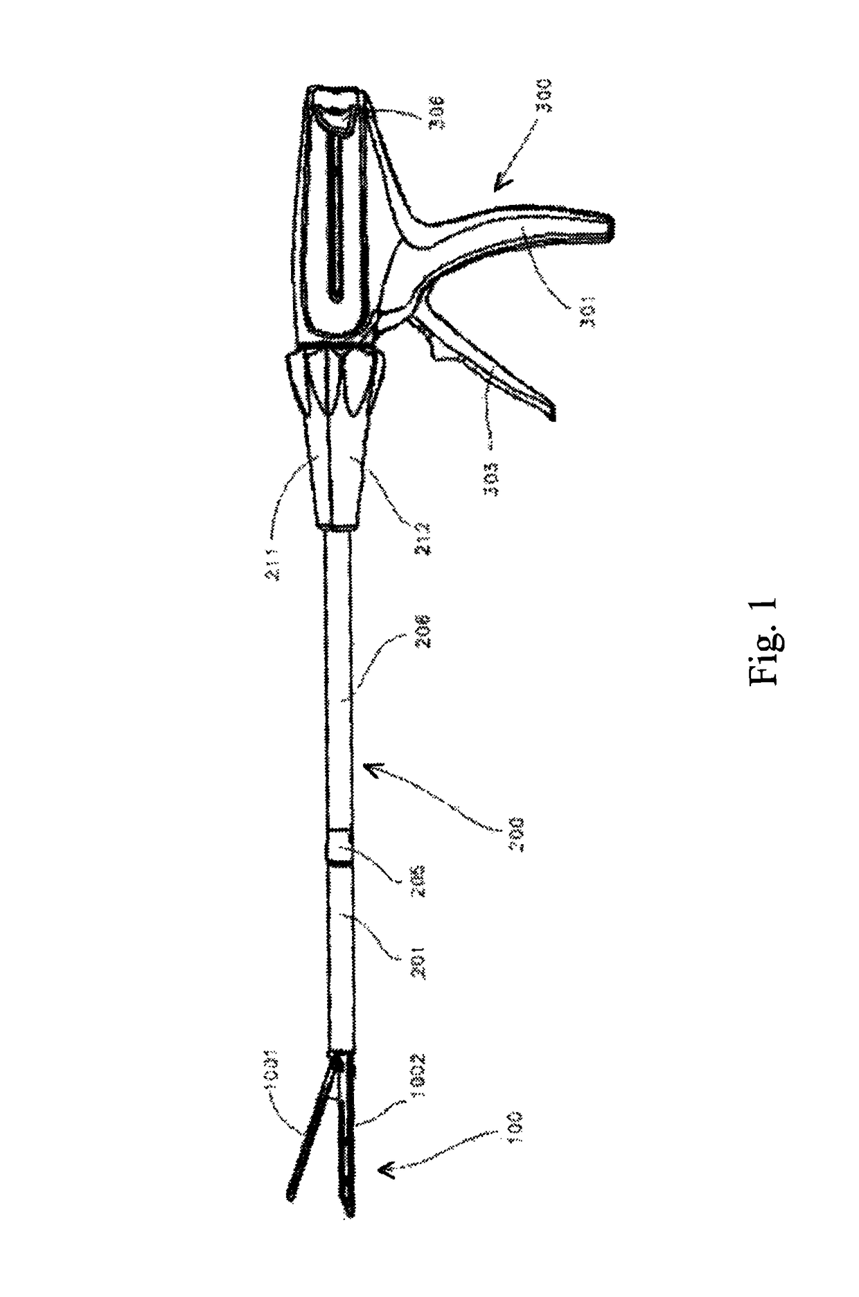
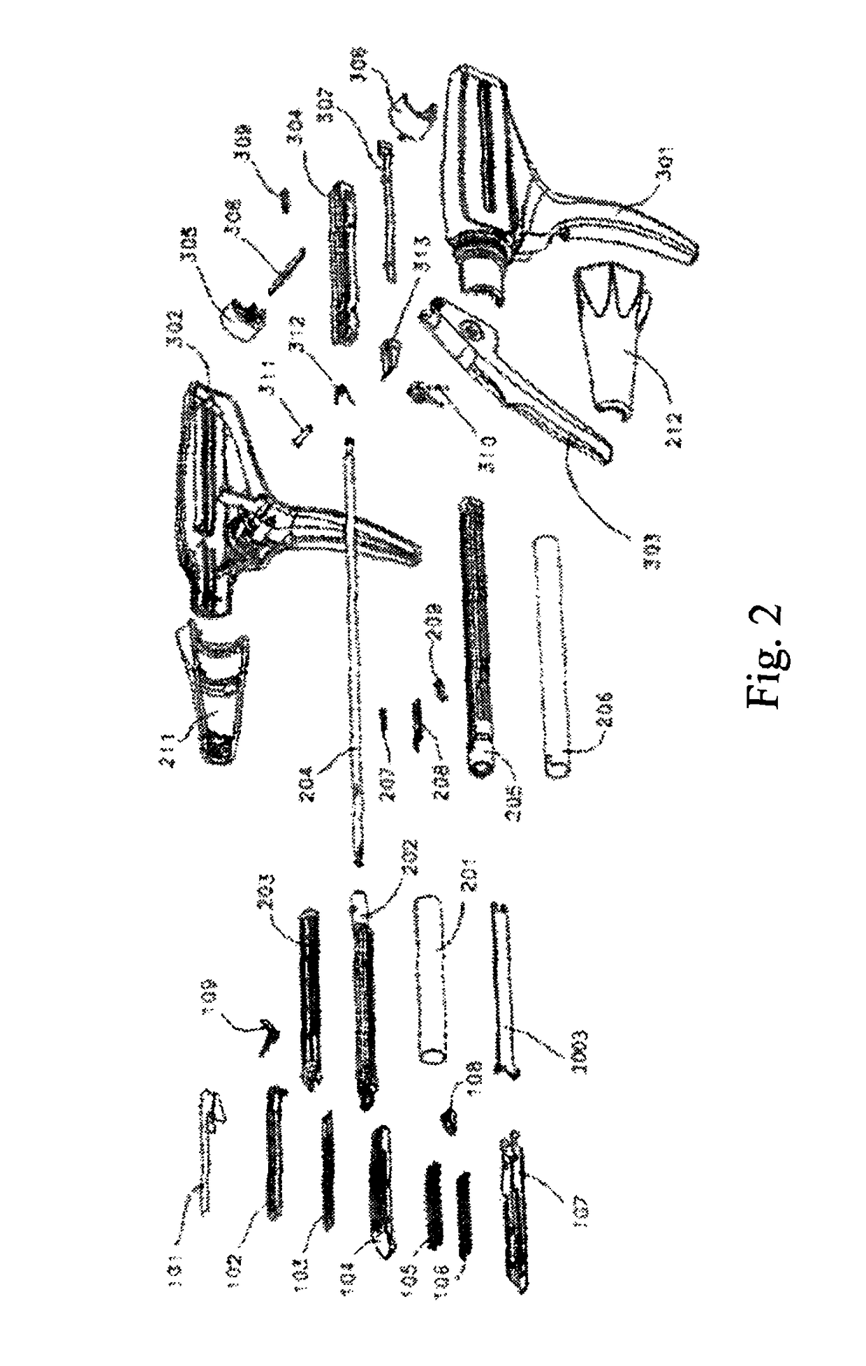
[0042]FIG. 1 to FIG. 10 show the schematic diagrams for the surgical apparatus improved according to the first embodiment of this invention. Specifically, in this embodiment, referr...


PUM


Abstract

An improved surgical apparatus actuator includes a nail bin assembly (1002), a nail anvil assembly (1001) connecting with the nail bin assembly (1002), and a drive assembly (1003) controlling the nail bin assembly (1002) and the nail anvil assembly (1001) to convert between opening and closing conditions. The nail anvil assembly (1001) includes a nail anvil plate (103) and a nail anvil seat (102), wherein the nail anvil plate (103) is provided on an inner side (1022) of the nail anvil seat (102), the nail anvil seat (102) has the structure, material and processing technology capable of providing high anti-bending performance, the nail anvil plate (103) is cold-punched from a thinner stainless steel sheet. Therefore, the processing difficulty of the components is reduced, and meanwhile, the ability of the actuator chuck to resist bending deformation is improved.

Description

CROSS REFERENCE OF RELATED APPLICATION[0001]This is a U.S. National Stage under 35 U.S.C 371 of the International Application PCT / CN2013 / 082025, filed Aug. 22, 2013, which claims priority under 35 U.S.C. 119(a-d) to CN 201210349356.7, filed Sep. 18, 2012.BACKGROUND OF THE PRESENT INVENTION[0002]Field of Invention[0003]This invention relates to a surgical apparatus, especially a kind of anastomat for surgical operation. More specifically, it relates to an improved surgical apparatus actuator.[0004]Description of Related Arts[0005]The working principle of surgical anastomat is to clamp tissues through the closing of two corresponding jaws (which are normally called nail anvil assembly and nail bin assembly) and then push the metal suturing nails in the anastomat nail bin out for molding and suture tissues together. In some anastomats, a cutter is installed to cut off sutured tissues.[0006]The anastomat with the above functions also includes actuator, intermediate connecting body and c...

Claims


Application Information

Patent Timeline
Patent Type & Authority Patents(United States)
IPC IPC(8): A61B17/072
CPCA61B17/07207A61B2017/07214A61B2017/00526A61B2017/00831A61B2017/07257
Inventor ZHENG, MINHUAZHANG, XINLIANGLI, ANHUAFENG, BOMA, JUNJUNSUN, JING
Owner EZISURG MEDICAL CO LTD
Why Eureka
Try Eureka