Supercharge Your Innovation With Domain-Expert AI Agents!

Method and apparatus for forming a stoma and a balloon catheter

a balloon catheter and stoma technology, which is applied in the field of balloon catheters, can solve the problems of poor sensitivity with which the transverse cross-sectional area of the inflatable element can be computed, and the reading of the pressure of the inflating medium adjacent the proximal end of the inflating medium accommodating the lumen does not accurately represent the proximal end of the catheter,

Active Publication Date: 2018-04-03
FLIP TECH LTD
View PDF44 Cites 0 Cited by
  • Summary
  • Abstract
  • Description
  • Claims
  • Application Information

AI Technical Summary

Benefits of technology

The invention is a device for monitoring a stoma (the opening through which a gastric band is inserted to treat obesity or gastrointestinal disorders) using an inflatable cuff. The device can detect changes in the size of the stoma and adjust the tightness of the gastric band accordingly to control the size of the stoma. This allows for automatic adjustment of the stoma size without the need to constantly monitor its size within the stomach. This simplifies the procedure and reduces the risk of complications. The device uses a block representation and cross-sectional views of a balloon catheter to determine the cross-sectional area and volume of the stoma.

Problems solved by technology

This is unsatisfactory due to the remoteness of the proximal end of the catheter from the inflatable element.
By virtue of the fact that the proximal end of the catheter is remote from the inflatable element, in general, the pressure of the inflating medium read at the proximal end of the catheter does not accurately represent the pressure of the inflating medium in the inflatable element, due to the fact that a pressure drop occurs along the lumen between the proximal and distal ends thereof.
Thus, in catheters of small transverse cross-sectional area a pressure reading taken of the inflating medium adjacent the proximal end of the inflating medium accommodating lumen does not accurately represent the pressure of the inflating medium in the inflatable element due to the pressure drop between the proximal end of the inflating medium accommodating lumen and the distal end thereof adjacent the inflatable element.
Furthermore, during inflating and deflating of the inflatable element, the pressure drop across the inflating medium accommodating lumen between the proximal end of the lumen and the distal end adjacent the inflatable element becomes significantly greater, and thus, a reading of the pressure of the inflating medium adjacent the proximal end of the inflating medium accommodating lumen would fail to produce an accurate indication of the pressure of the inflating medium within the inflatable element.
However, a problem with such balloon catheters is that at locations along the inflatable element where the inflatable element is inflated to a relatively large diameter, the sensitivity with which the values of the transverse cross-sectional area of the inflatable element can be computed is relatively poor.
Since the determination of the volume of the inflatable element between two selected sensing electrodes requires a determination of the values of the transverse cross-sectional area of the inflatable element adjacent the respective sensing electrodes which are located between the two selected sensing electrodes between which the volume is to be determined, if the values of the transverse cross-sectional area adjacent these sensing electrodes cannot be accurately determined, it will be impossible to accurately determine the volume of the relevant part of the inflatable element.
Therefore, in cases where a balloon catheter is required to determine the values of the transverse cross-sectional area of a vessel or lumen of varying transverse cross-sectional area, and in particular, where the transverse cross-sectional area varies significantly, in general, it is difficult if not impossible to accurately determine the values of the transverse cross-sectional area of the vessel at locations where the transverse cross-sectional area is relatively large by comparison to other locations of the vessel where the transverse cross-sectional area is relatively small.
However, in many cases in the digestive system, particularly in the more remote locations, for example, in the intestine, or at locations where the remote site is diseased, or where the catheter must pass through a diseased site in order to gain access to the remote site, it is not possible to guide a catheter to a remote site without the assistance of a guide wire.
In many cases, particularly, in the case of a balloon catheter where a number of lumens extending axially through the catheter are required to communicate with an inflatable element, such as a balloon on the distal end of the catheter, the transverse cross-section of the catheter may be such that there is insufficient room for a further lumen to accommodate a guide wire.
In many such cases, with such a number of lumens, all of which require to be sealed there may be insufficient room within the cross-section of the catheter for a further lumen to accommodate a guide wire.
Additionally, by virtue of the fact that in such cases all the lumens must be mutually sealed from each other, such lumens are unavailable to accommodate a guide wire.
Obesity is a serious problem nowadays amongst adults, adolescents, and indeed children.
However, dieting in seriously obese subjects, in general, has a poor success rate.
The remaining part of the stomach between the stoma and the intestine becomes ineffective.
Thus, gastric banding reduces the effective digestive volume of the stomach, thereby leading to weight loss.
Thus, since a surgeon does not have access to the interior of the stomach during forming of the stoma, measuring of the internal transverse cross-sectional area of the stoma during inflating of the cuff of a gastric band cannot be carried out.
The need for a subject to attend at frequent consultations with a surgeon subsequent to the carrying out of a procedure to form a stoma in the stomach of the subject in order to set the stoma at the appropriate internal transverse cross-sectional area is undesirable, and furthermore, places a high cost burden on the public health service.

Method used


Image

  • Method and apparatus for forming a stoma and a balloon catheter
  • Method and apparatus for forming a stoma and a balloon catheter
  • Method and apparatus for forming a stoma and a balloon catheter

Examples


Embodiment Construction

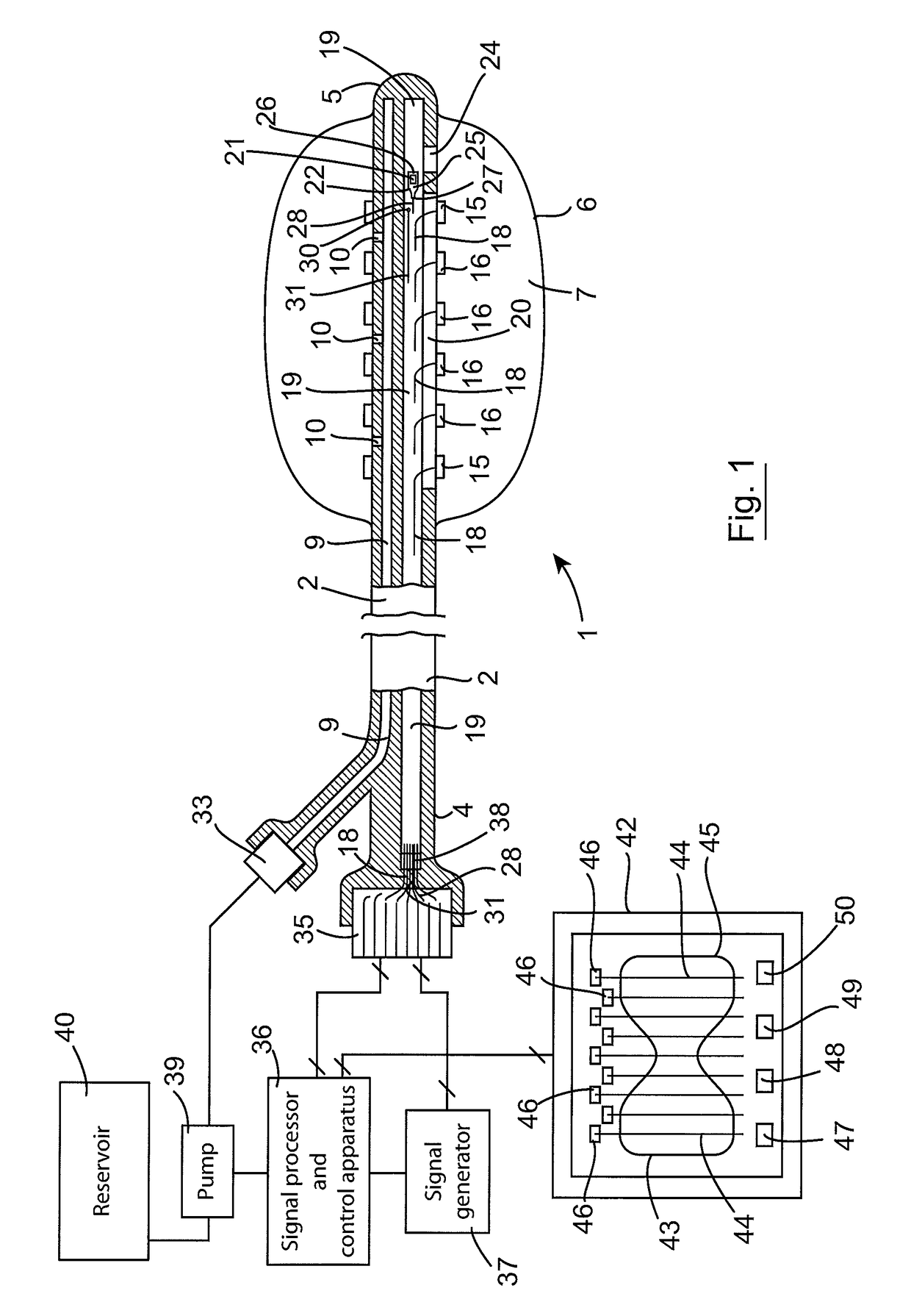
[0155]Referring to the drawings and initially to FIGS. 1 to 7 thereof, there is illustrated apparatus according to the invention comprising a balloon catheter also according to the invention, indicated generally by the reference numeral 1 for accessing a remote site in a body of a human or animal subject. The balloon catheter 1 is particularly suitable for use in a method for forming a stoma in the stomach of a human subject and for monitoring the internal transverse cross-sectional dimension, such as the internal transverse cross-sectional area or diameter of the stoma during formation thereof. The formation of a stoma in the stomach of a human or animal subject will be described in more detail below. However, it will be readily apparent to those skilled in the art that the balloon catheter 1 may be used for many other purposes, where it is desired to determine a value of a transverse cross-sectional dimension such as the diameter and / or the area of a lumen, a vessel, a sphincter o...


PUM


Abstract

A balloon catheter comprises a catheter and a balloon located on the distal end of the catheter. A pair of stimulating electrodes for receiving a constant current stimulating signal when the balloon is inflated with an electrically conductive medium and a plurality of sensing electrodes for producing voltage response signals are located on the catheter. The voltage response signals are indicative of the values of the transverse cross-sectional area of the balloon adjacent the sensing electrodes. A first lumen accommodates the inflating medium to and from the balloon, and a second lumen accommodates electrically conductive wires to the stimulating and sensing electrodes. A pressure sensing element is located in a protective housing in the second lumen, and communicates through a communicating opening in the protective housing and through a communicating port in the catheter with a hollow interior region of the balloon. The balloon catheter may also be provided with a guide wire engaging element for engaging a guide wire externally of the balloon catheter.

Description

CROSS REFERENCE TO RELATED APPLICATIONS[0001]This application is a divisional of U.S. application Ser. No. 13 / 255,195, which is the National Stage of International Application No. PCT / IE2010 / 000011 filed Mar. 9, 2010, which claims priority of Irish Patent Application No. S2009 / 0184 filed Mar. 9, 2009, Irish Patent Application No. S2009 / 0310 filed Apr. 21, 2009, and Irish Patent Application No. S2009 / 0441 filed Jun. 4, 2009. The above noted applications are incorporated herein by reference in their entirety.BACKGROUND OF THE INVENTION[0002]The present invention relates to a balloon catheter, and in particular, though not limited to a balloon catheter of the type for determining the volume and / or transverse cross-sectional diameter or area of a vessel, lumen, sphincter or stoma. The invention also relates to a catheter, and to a method and apparatus for monitoring the transverse cross-section of a stoma, and particularly for monitoring the transverse cross-section of a stoma during fo...

Claims


Application Information

Patent Timeline
Patent Type & Authority Patents(United States)
IPC IPC(8): A61M29/00A61B5/107A61M25/10A61B5/00A61F5/00A61M25/00A61F2/958
CPCA61B5/1076A61B5/4238A61B5/6853A61F5/0063A61M25/10184A61M25/10187A61B5/42A61M2210/1064A61F2005/002A61M25/10A61M25/1002A61M25/1018A61M2025/0002A61M2025/1086A61M2025/1088A61M2025/1093
Inventor O'DEA, JOHNMCHUGH, ADRIANBAMBURY, EOIN
Owner FLIP TECH LTD
Features
  • R&D
  • Intellectual Property
  • Life Sciences
  • Materials
  • Tech Scout
  • Unparalleled Data Quality
  • Higher Quality Content
  • 60% Fewer Hallucinations
Learn More