Counter counterfeit technology

a counterfeit technology and technology of counters, applied in the field of counterfeit technology, can solve problems such as system failure or system performance degradation, and achieve the effects of cost-effective manufacturing, sufficient resolution and cost-effectiveness

Active Publication Date: 2018-04-03
RAYTHEON CO
View PDF11 Cites 0 Cited by
  • Summary
  • Abstract
  • Description
  • Claims
  • Application Information

AI Technical Summary

Benefits of technology

[0005]Using the distinctive pattern of resonance elements as a counterfeit technology is advantageous in that the identification patch has a unique optical signature that may be difficult to replicate. The identification patch may also be formed to have a particular optical signature within a specific portion of the electromagnetic spectrum, such as the ultraviolet, visible, or infrared light region. Another advantage is that the identification patch may be cost-effectively manufactured, based on the varying materials that may be used. Using the roll-to-roll printing process is also cost-effective in that the process enables the forming of a meter scale sheet of material with nanoscale features in several minutes. The patches can be as small as a few millimeters on a side, so the meter scale sheet of material will yield 1000s of patches. In addition to cost-effectiveness, another advantage of using the roll-to-roll printing process is that even the slightest variations in rollers or materials may create distinctive patterns in each of the patches. If the spectrometer has sufficient resolution, variations of each patch due to local variations in the manufacturing process along with distinctive patterns due to the variations will enable each of these patches to have unique optical properties. Still another advantage of using the plasmonic resonance structure is that the identification patch may also be used in conjunction with conventionally-used identifiers, such as barcodes, to provide a further verification step to authenticate the component. Another advantage is that multiple patches, with different wavelengths may be combined to provide a further verification. Using the plasmonic resonance structure for additional verification may be particularly advantageous for components used in defense and medical applications.

Problems solved by technology

Using an improper or counterfeit article may result in failure of the article when used that can lead to degraded system performance or system failure.

Method used


Image

  • Counter counterfeit technology
  • Counter counterfeit technology
  • Counter counterfeit technology

Examples


Embodiment Construction

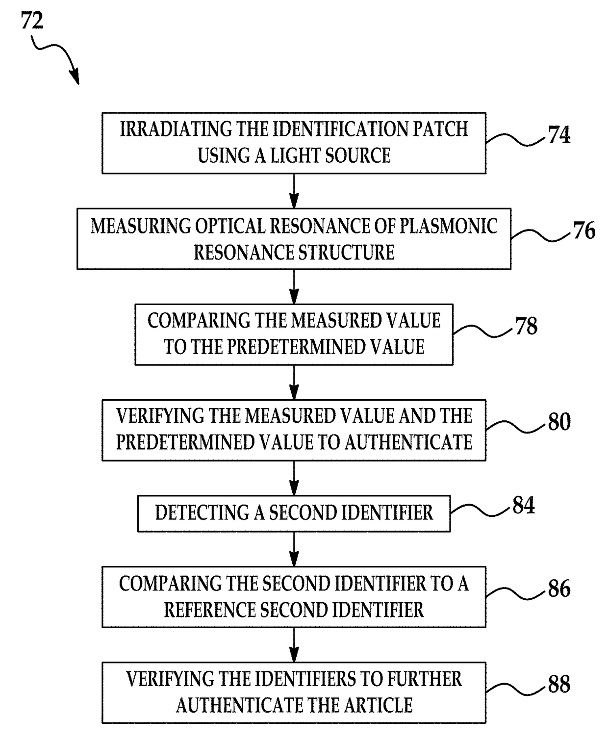
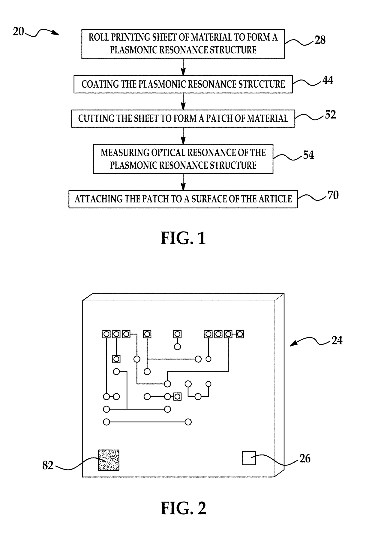
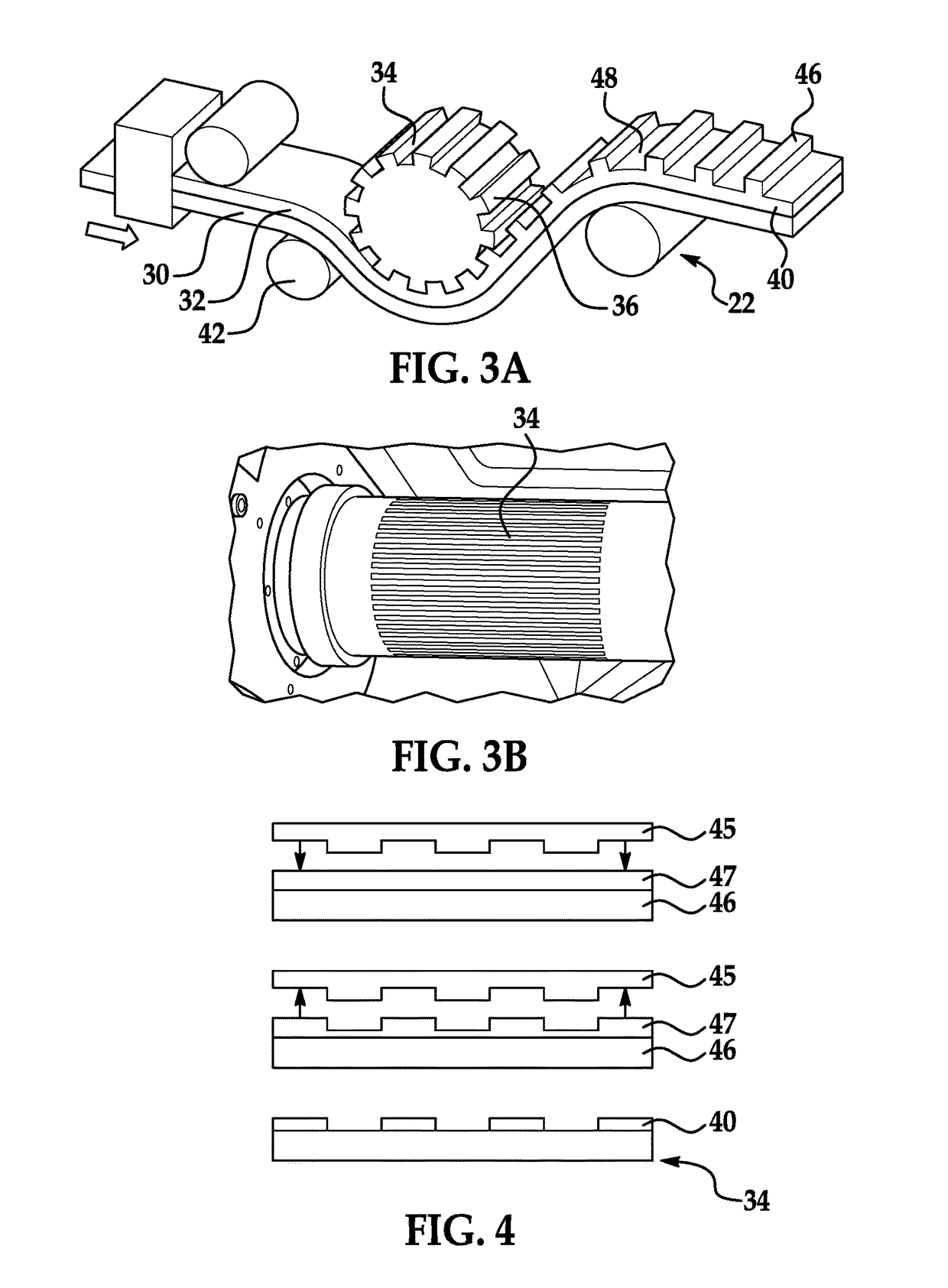
[0037]The principles described herein have application for authenticating any suitable article in various applications. Examples of suitable articles include manufactured parts or components and paper documents. Examples of paper documents include contracts, checks, passports, birth certificates, driver's licenses, medical forms, paper currency, and any type of legal document or personal identification document. Other suitable articles may include commercial products. In defense applications, various parts or components may require authentication prior to use. Producing a counterfeit-proof article may include manufacturing a roll-to-roll printed patch of material with a plasmonic resonance structure and attaching the patch of material to the article. The plasmonic resonance structure has an ordered pattern of resonance elements that produces a distinctive and measurable optical properties to enable verification of the authenticity of the article.

[0038]Referring now to FIGS. 1-4, a m...


PUM

PropertyMeasurementUnit
widthaaaaaaaaaa
heightaaaaaaaaaa
widthaaaaaaaaaa

Abstract

An identification patch having a plasmonic resonance structure may be used to ensure that an article is counterfeit-proof. The identification patch may be formed by a printing process, such as roll-to-roll printing or nanoimprinting, to create a distinctive ordered pattern of resonance elements. When the plasmonic resonance structure is irradiated, the ordered pattern of resonance elements produces a unique spectral response that is associated only with the counterfeit-proof article. The counterfeit-proof article may be a metal component or an integrated circuit. The resonant absorption of the plasmonic resonance structure may be measured to verify the authenticity of the article before use of the article.

Description

FIELD OF THE INVENTION[0001]The invention relates to a method and system for authenticating articles and for detecting counterfeit articles by way of a small piece of material attached to the article and a laser source and spectrometer.DESCRIPTION OF THE RELATED ART[0002]Various applications require verifying the authenticity of an article, such as a component or part, prior to use of the article. Particularly for safety and security purposes, authenticating the article ensures that the proper article is being provided for use in a particular application. For example, a computer processor is a component that may require authentication before use in a defense application. Using an improper or counterfeit article may result in failure of the article when used that can lead to degraded system performance or system failure.[0003]Due to technology advances, the manufacturing of counterfeit articles has become easier and therefore more prevalent. Conventionally-used identifiers, such as s...

Claims


Application Information

Patent Timeline
Patent Type & Authority Patents(United States)
IPC IPC(8): G06K9/74G06K19/16G06K7/10H01L23/544G01N21/65G01N21/552B42D25/387B42D25/445B42D25/382B42D25/21B42D25/328
CPCB42D25/328B42D25/21B42D25/382B42D25/387B42D25/445G01N21/658G06K7/10861G06K19/16H01L23/544G01N21/553H01L2223/54433
Inventor UYENO, GERALD P.
Owner RAYTHEON CO
Why Eureka
Try Eureka