Wind turbine blade with lightning protection

a technology blades, which is applied in the field of wind turbine blades with lightning protection, can solve the problems of smt b damage, problems such as problems such as problems such as damage to smt b, and achieve the effect of reducing the risk of damage and reducing the risk of insufficient conta

Active Publication Date: 2018-04-03
VESTAS WIND SYST AS
View PDF28 Cites 0 Cited by
  • Summary
  • Abstract
  • Description
  • Claims
  • Application Information

AI Technical Summary

Benefits of technology

[0019]The invention provides a method of making a wind turbine blade in which contact between the mould surface of the second mould half and the metallic lightning receptor component is substantially avoided. In this way, the risk of the second mould half clashing with the metallic lightning receptor component in the event of a misalignment of the mould halves is significantly reduced or avoided. This in turn reduces the risk of damage to the metallic lightning receptor component, and reduces the risk of insufficient contact being made between the half shells.
[0026]In one embodiment, the step of making the first half shell involves a curing process, and the step of integrating the metallic lightning receptor component with the first half shell occurs after the curing process. This allows the first half shell to be fully formed prior to integration of the metallic lightning receptor component.
[0029]From a second aspect, the invention resides in a mould assembly for a wind turbine blade, the mould assembly comprising a first mould half for moulding a first half shell of the wind turbine blade and a second mould half for moulding a second half shell of the wind turbine blade, each half shell comprising a composite material, the mould assembly having an open position in which the mould halves are spaced apart, and each mould half comprising a mould surface and a closed position in which the mould halves are brought together, wherein, in use, a metallic lightning receptor component is integrated with the first half shell and the mould assembly is configured such that a clearance region is defined between the mould surface of the second mould half and the metallic lightning receptor component when the mould assembly is in the closed position, such that contact between the mould surface of the second mould half and the metallic lightning receptor component is substantially avoided.
[0030]The invention provides a mould assembly in which contact between the mould surface of the metallic lightning receptor component and the second mould half is substantially avoided as a result of the clearance region. The risk of the second mould half clashing with the metallic lightning receptor component in the event of a misalignment of the mould halves is therefore reduced. This in turn reduces the risk of damage to the metallic lightning receptor component, and reduces the risk of insufficient contact between the half shells.
[0033]To reduce movement of the metallic lightning receptor component as the wind turbine blade is made, the mould assembly preferably comprises a support to hold the metallic lightning receptor component in place with respect to the first half shell during closing of the mould assembly. The support acts a jig for the metallic lightning receptor component.

Problems solved by technology

Although such a method provides a simple way of integrating an SMT 12 with a wind turbine blade 10, problems can arise if there is any misalignment between the two mould halves 20 when the mould is closed.
In extreme cases, this can damage the SMT 12, or even lead to the SMT 12 breaking away from the lower half shell 16.
Such clashing can also cause damage to the mould itself.
For example, the smooth inner surface of the mould may be damaged, which can be problematic for future use of the mould.
Modern wind turbine blades may be over eighty meters in length, and it will be appreciated that when manufacturing blades of this size, misalignments are difficult to avoid.
In particular, it is difficult to achieve precise alignment simultaneously at both the blade root and at the blade tip.
Thus, for manufacturing processes where alignment at the root is crucial, alignment of the half shells at the tip is particularly difficult, and the above problem is particularly prevalent.

Method used


Image

  • Wind turbine blade with lightning protection
  • Wind turbine blade with lightning protection
  • Wind turbine blade with lightning protection

Examples


Embodiment Construction

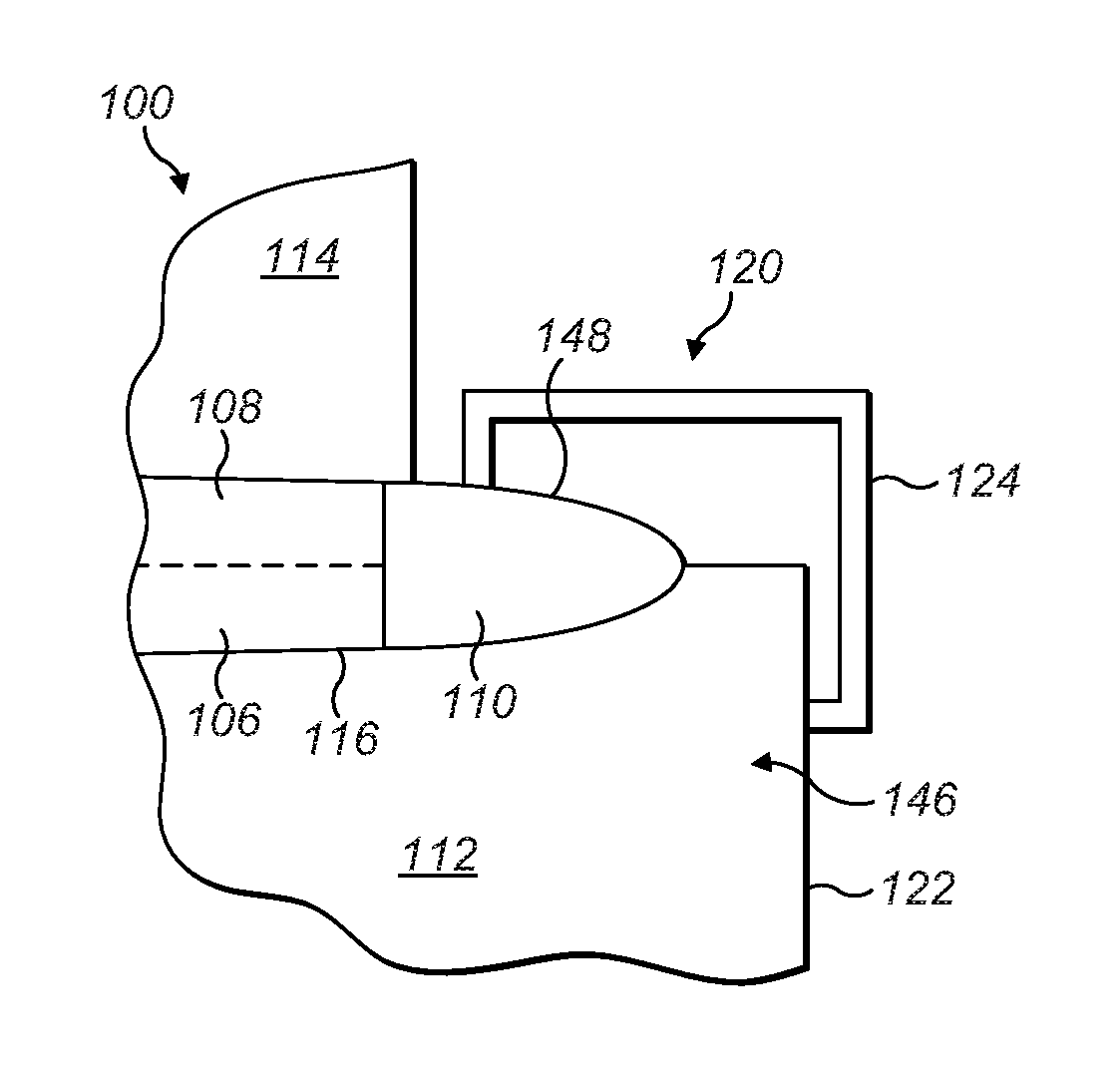
[0048]FIG. 4 shows a cross-sectional view of a mould assembly 100 according to an embodiment of the invention. Specifically, the mould assembly 100 is for moulding a wind turbine blade 102 that comprises an outer shell 104 formed from two half shells 106, 108, and a lightning receptor in the form of a solid metal tip (SMT) 110 integrated with the outer shell 104. Each half shell 106, 108 of the outer shell 104 is moulded from glass-fibre reinforced plastic (GRP).

[0049]The mould assembly 100 comprises two mould halves: a first mould half 112 for moulding the first half shell 106, and a second mould half 114 for moulding the second half shell 108. The mould assembly 100 has an open position in which the two mould halves 112, 114 are spaced apart, and a closed position in which the two mould halves 112, 114 are brought together, as shown in FIG. 4.

[0050]Each mould half 112, 114 extends along a longitudinal axis and comprises an inner mould surface 116 (FIG. 5) for moulding its respecti...


PUM

PropertyMeasurementUnit
lengthaaaaaaaaaa
metallicaaaaaaaaaa
distanceaaaaaaaaaa

Abstract

A method of making a wind turbine blade (10) having a metallic lightning receptor (110) is described. The method comprises configuring a wind turbine blade (10) mold assembly (100) such that a clearance region (120) is defined between a mold surface (116) of at least one mold half (112, 114) and a majority of a metallic lightning receptor component (110) when the mold assembly (100) is closed, such that contact between that mold half (112, 114) and the metallic lightning receptor component (110) is substantially avoided. In certain embodiments of the invention, one or both mold halves (112, 114) are truncated such that the metallic lightning receptor component (110) projects from the mold (100) when the mold (100) is closed.

Description

TECHNICAL FIELD[0001]The present invention relates generally to rotor blades for wind turbines and to methods of manufacturing wind turbine blades. More specifically, the present invention relates to wind turbine blades including a solid metal tip that is formed as a separate piece before being joined to the remainder of the blade.BACKGROUND[0002]Solid metal tips (SMTs) are typically integrated into wind turbine blades to address the problem of lightning strikes. The SMT acts as a lightning receptor that receives lightning and discharges it to a ground potential via conductors that extend inside the blade, nacelle, and tower of the wind turbine. SMTs therefore allow lightning to be discharged safely and minimise the risk of damage to the wind turbine from lightning strikes.[0003]To put the invention into context and to explain certain problems suffered by the prior art, reference will firstly be made, by way of example, to FIGS. 1 to 3 of the accompanying drawings, in which:[0004]FI...

Claims


Application Information

Patent Timeline
Patent Type & Authority Patents(United States)
IPC IPC(8): B29C33/00F03D80/30B29C65/00F03D1/06B29C33/12B29C65/48B29C65/78B29L31/08
CPCF03D1/0675B29C33/12B29C66/7212B29C33/005F03D80/30B29C65/48B29C65/78B29C65/7802B29C65/7841B29C66/543B29C66/721B29C66/73141B29C66/742B29C66/81423B29C65/483B29C66/301B29C66/72141B29K2995/0005B29L2031/085F05B2230/60Y02E10/721Y02P70/523B29K2309/08Y02E10/72Y02P70/50F05B2240/307
Inventor RAJASINGAM, DAMIENCOLLARD, TOBY
Owner VESTAS WIND SYST AS
Why Eureka
Try Eureka