
Three-dimensional resolution gauge for evaluating performance of tomographic imaging systems

a technology of tomographic imaging and three-dimensional resolution, applied in the field ofphantom tomographic imaging system performance evaluation, to achieve the effect of x or y versus, reducing or reducing the z

Active Publication Date: 2018-04-03
THE PHANTOM LABORATORY INCORPORATED
View PDF16 Cites 3 Cited by
  • Summary
  • Abstract
  • Description
  • Claims
  • Application Information

AI Technical Summary

Benefits of technology

[0011]Each segment or grouping is preferably implemented by spaced apart fins or ramps (or other similar repetitive structures) located in spaced apart parallel planes, all oriented at a constant set acute angle relative to the reference x-y imaging plane. It can be noted that most tomographic imaging systems using square acquisition matrices (square pixels), e.g. 256×256, or 512×512, produce images with the same x and y resolution level; so that the segments or groupings can be aligned with either the x or the y axis, enabling the repetition rate to be basically one dimensional (x or y). In the event of a non-symmetric x,y resolution e.g. 256×512, the gauge can be moved from the x to the y alignment, while still showing the z-axis resolution effect.
[0016]Although amenable to quantitative analysis (in a manner similar to that described in commonly assigned U.S. Pat. No. 8,348,508 B2), the new resolution gauge advantageously provides a physician, clinician or other user of the tomographic imaging system with a single visual image, test and / or analysis of 3D (voxel) resolution which affords easy, immediate and intuitive understanding of image resolution simultaneously and effectively in 3 dimensions.
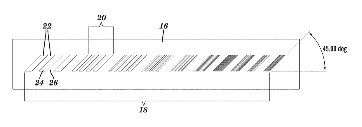
[0022]Alternatively, the common acute angle may be set to less than 45 degrees to augment weight of the slice thickness z direction resolution, or set to more than 45 degrees to diminish weight of the slice thickness z direction resolution.

Problems solved by technology

Thus, current CT resolution gauges, in deliberately ignoring or minimizing the z-axis effect of the gauge, could tend to mislead the physician or observer to think that the resolution as seen from the gauge represents the resolution as might be achieved in the actual patient anatomy on a corresponding CT scan, rather than just in the 2D resolution gauge.

Method used


Image

  • Three-dimensional resolution gauge for evaluating performance of tomographic imaging systems
  • Three-dimensional resolution gauge for evaluating performance of tomographic imaging systems
  • Three-dimensional resolution gauge for evaluating performance of tomographic imaging systems

Examples


Embodiment Construction

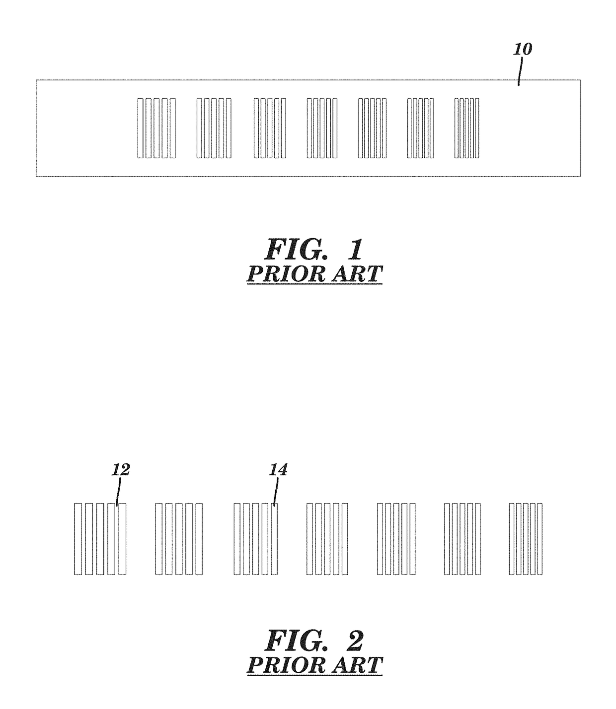
[0034]FIGS. 1 and 2 illustrate a conventional in-plane, 2-dimensional high resolution gauge 10. As one moves from left to right, it becomes more difficult to identify the white lines (spaces) 12 between the black lines (bars) 14. So basically, the better the in-plane or x-y imaging resolution, the finer the pattern that can be discerned. However, such in-plane gauges fail to consider z axis effects on image resolution in tomographic imaging systems.

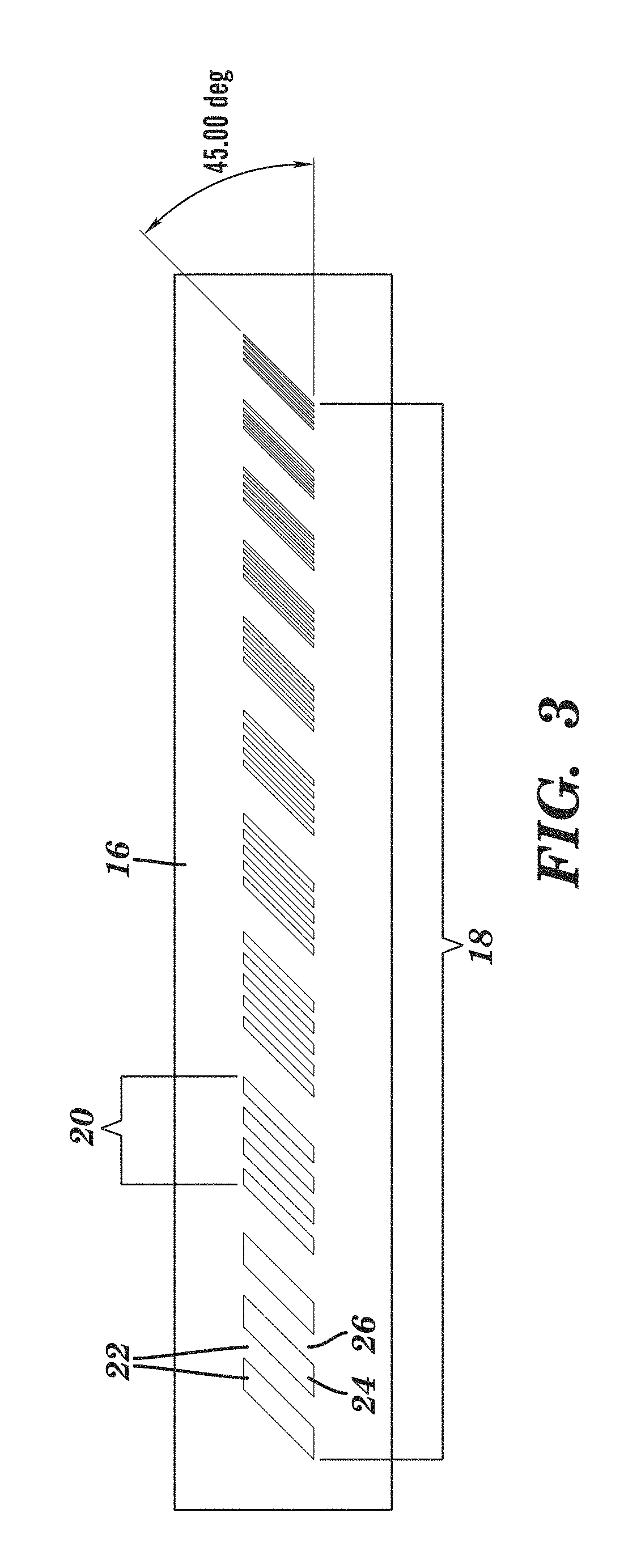
[0035]FIG. 3 is a schematic side view of an example of a 45° resolution gauge 16, constructed according to the principles of the present invention. The gauge includes a series 18 of segments or groupings 20 of 3-dimensional line pairs 22. Each grouping 20 is composed of angled fins or ramps 24, set at a common constant acute angle of 45°, in spaced apart parallel planes. Each line pair 22 comprises a single ramp 24 and an adjacent intermediate space 26. From one end to the other end of the gauge 16, e.g., from left to right in FIG. 3, the...


PUM


Abstract

A three-dimensional resolution gauge for evaluating performance of a tomographic imaging system includes a series of groupings of 3-dimensional line pairs. All of the line pairs are oriented at a common set acute angle relative to a reference x-y imaging plane. The frequency of the line pairs of respective groupings of the series vary from highest density to lowest density corresponding to fine resolution and coarse resolution, respectively. Imaging of the series of groupings by the tomographic imaging system provides, in a single scan, a simultaneous visualization of combined effects of x-y in-plane resolution and slice thickness z direction resolution.

Description

CROSS-REFERENCE TO RELATED APPLICATION[0001]This application claims priority of Provisional Application No. 62 / 150,961, filed on Apr. 22, 2015, the entire contents of which is hereby incorporated by reference herein.FIELD OF THE INVENTION[0002]This invention relates, in general, to a phantom for evaluating performance of a tomographic imaging system and, more particularly, to a three-dimensional resolution gauge that provides, via a single scan of a single test object, a simultaneous visualization of combined effects of x-y in-plane resolution and slice thickness z direction resolution.BACKGROUND ART[0003]The growing trend toward 3D imaging involving Volume Computed Tomography (CT) scanners and the use of 3D and Multi Planar Reconstruction (MPR) techniques leads to the need for phantoms and test methods that reveal to the radiologist and physicist actual 3D resolution, i.e., measures involving not only in-plane (x,y) resolution and related Modulation Transfer Functions (MTF's) but a...

Claims


Application Information

Patent Timeline
Patent Type & Authority Patents(United States)
IPC IPC(8): G06K9/00G06T15/08G06T11/00A61B6/00
CPCG06T15/08G06T11/008A61B6/583G06T2211/40
Inventor GOODENOUGH, DAVID J.LEVY, JOSHUA R.
Owner THE PHANTOM LABORATORY INCORPORATED
Learn More