
Back light unit and liquid crystal display using the same

a backlight unit and liquid crystal display technology, applied in the field of backlight units and liquid crystal displays, can solve the problem of limiting the thickness of the backlight unit, and achieve the effects of reducing the number of light sources, minimizing luminance variation, and excellent heat-resistant properties and optical properties

Active Publication Date: 2018-04-10
LG INNOTEK CO LTD
View PDF33 Cites 1 Cited by
  • Summary
  • Abstract
  • Description
  • Claims
  • Application Information

AI Technical Summary

Benefits of technology

The present invention replaces the essential light guide plate of a general back light unit with a resin layer made of an oligomer. This reduces the number of light sources needed, minimizes color variations when the unit is exposed to high temperatures for a long time, and exhibits excellent heat-resistant and optical properties.

Problems solved by technology

Accordingly, this light guide plate is basically used as an essential element for the back light unit; however, there is a limitation to thinning a thickness of the back light unit due to its own thickness of the light guide plate.

Method used


Image

  • Back light unit and liquid crystal display using the same
  • Back light unit and liquid crystal display using the same
  • Back light unit and liquid crystal display using the same

Examples


Embodiment Construction

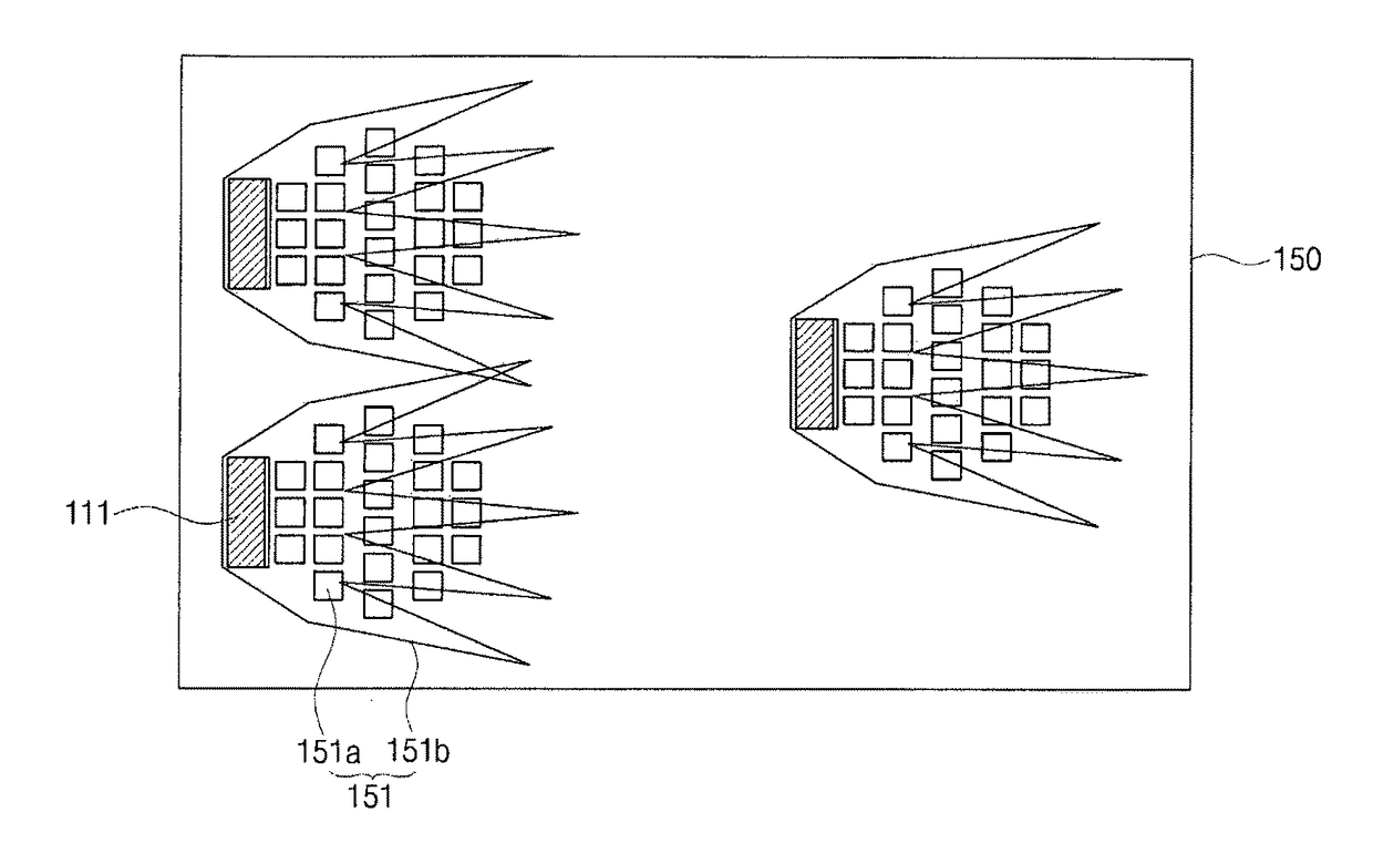
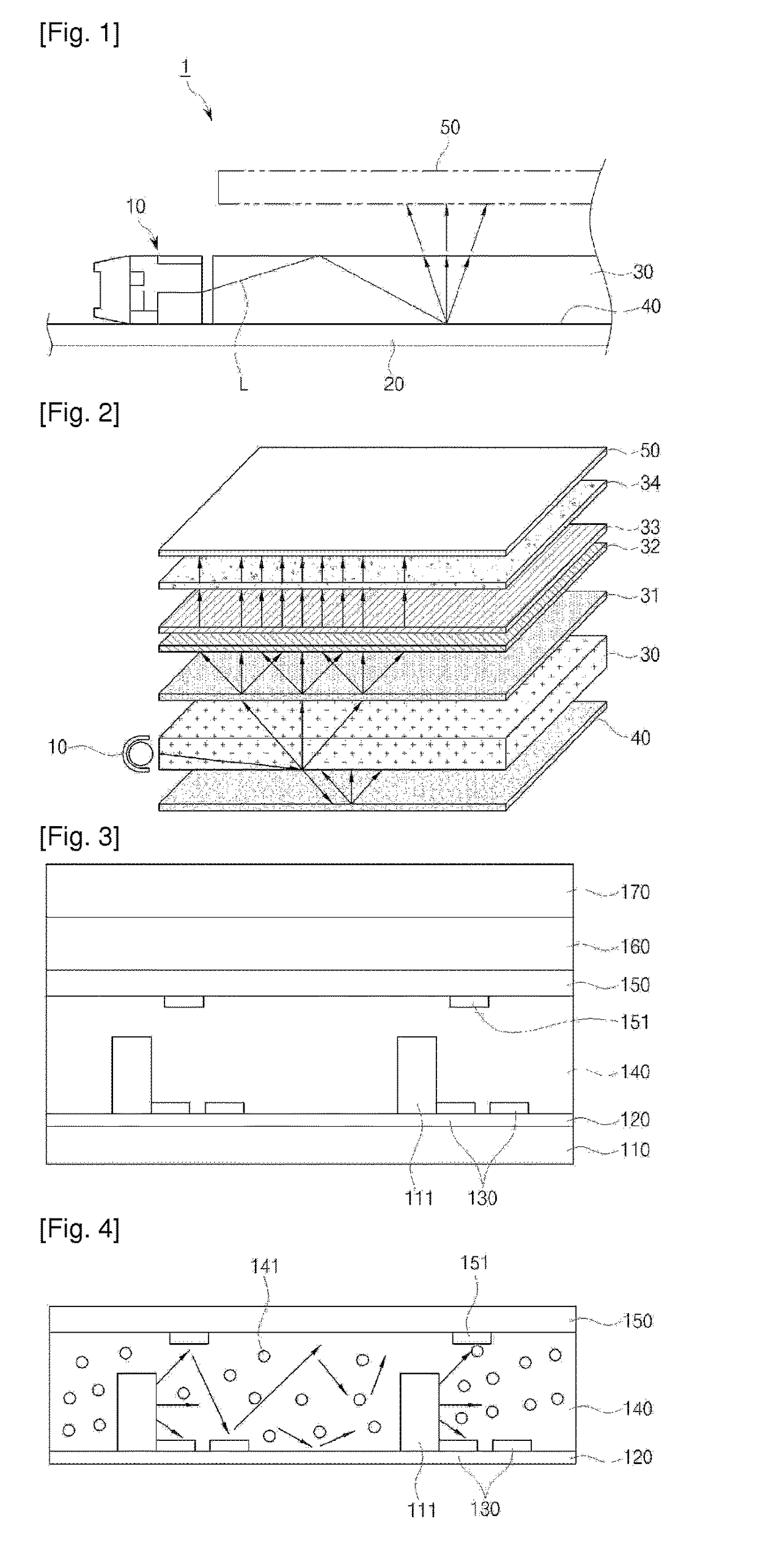
[0041]Exemplary embodiments of the present invention will be described below in detail with reference to the accompanying drawings. Wherever possible, the same reference numerals will be used to refer to the same elements throughout the specification, and a duplicated description thereof will be omitted. It will be understood that although the terms “first”, “second”, etc. are used herein to describe various elements, these elements should not be limited by these terms. These terms are only used to distinguish one element from another element.

[0042]A gist of the present invention relates to provide a back light unit in which a light guide plate is removed from a prior back light unit and it is formed with a resin layer mainly consisting of an oligomer and thereby minimizing luminance variations at a high temperature and decreasing greatly a thickness of a whole back light unit and further the number of a light source.

[0043]FIG. 3 and FIG. 4 are views illustrating main constitutional...


PUM

PropertyMeasurementUnit
thicknessaaaaaaaaaa
thicknessaaaaaaaaaa
humidityaaaaaaaaaa

Abstract

Provided is a back light unit comprising a plurality of LED light source formed on a printed circuit board and a resin layer which is laminated on the LED light source and forwardly induces diffusion of the emitted light wherein the resin layer is made of synthetic resin comprising an oligomer. According to the present invention, an essential light guide plate for a general back light unit configuration is removed and a resin layer mainly consisting of an oligomer is used to guide the light source, and thereby decreasing the number of the light source, minimizing luminance variation when the unit is lighted at a high temperature and kept it for a predetermined time period, and implementing excellent heat-resistant property and optical property.

Description

CROSS-REFERENCE TO RELATED APPLICATIONS[0001]This application is the U.S. national stage application of International Patent Application No. PCT / KR2011 / 006213, filed Aug. 23, 2011, which claims priority to Korean Application No. 10-2010-0133431, filed Dec. 23, 2010, the disclosures of each of which are incorporated herein by reference in their entirety.TECHNICAL FIELD[0002]The present invention relates to a backlight unit and a liquid crystal display using the backlight unit in which a light guide plate is removed and thereby thinning the backlight unit and ensuring light efficiency.BACKGROUND ART[0003]In general, a liquid crystal display (LCD) refers to as a display device in which by separately supplying data signals according to image information to pixels arranged in a matrix type and adjusting light transmission rates of the pixels, images can be adjusted to desired images wherein since it does not self-emit light, a back light unit is arranged on a rear surface thereof to disp...

Claims


Application Information

Patent Timeline
Patent Type & Authority Patents(United States)
IPC IPC(8): G02F1/1335F21V8/00F21V3/00
CPCG02F1/133605G02B6/0023G02B6/0073G02F1/133603G02F2202/28G02B6/0065G02F1/133606G02F2202/023C09K2323/035C09K2323/03
Inventor HUR, SICPARK, PENG SAMJUNG, TAE OUNPARK, KWANG HOPARK, MOO RYONG
Owner LG INNOTEK CO LTD
Learn More