
System using a subcircuit shared between capacitors for providing reactive power

a technology of reactive power and capacitors, applied in the field of power systems, can solve the problems of resonance, significant amplification of 300 hz voltage/current, eventual damage to capacitors, etc., and achieve the effect of reducing the total cost and space requirements for mitigating resonance or filtering harmonics associated with multiple switchable capacitors, and ensuring the effect of resonance reduction

Active Publication Date: 2018-04-10
XU WILSUN
View PDF12 Cites 8 Cited by
  • Summary
  • Abstract
  • Description
  • Claims
  • Application Information

AI Technical Summary

Benefits of technology

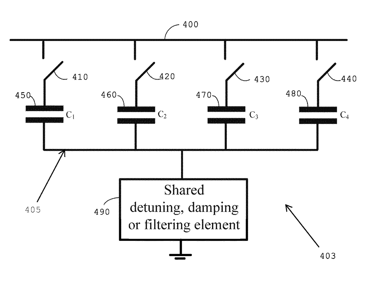
The patent describes a way to reduce the cost and space requirements for multiple switchable capacitors by using a common detuning, damping, or filtering element. This element can be designed to provide adequate detuning, damping, or filtering capability for all possible on / off combinations of the capacitors. This results in a more efficient and cost-effective way to mitigate resonance or filtering harmonics associated with multiple switchable capacitors.

Problems solved by technology

Although shunt capacitors are a simple and effective reactive power compensation apparatus, they suffer from the problem of resonance.
If resonance occurs, this can lead to a significant amplification of the 300 Hz voltage / current and eventual damage to the capacitors.
Shunt capacitors can thus be negatively affected by harmonic resonance.
However, this method does not always work if the system exhibits capacitive impedance at certain frequencies.
The damping element's resistive component can damp the magnitude of resonance.
The cost and space requirements for implementing these changes increase with the number of switchable capacitors.

Method used


Image

  • System using a subcircuit shared between capacitors for providing reactive power
  • System using a subcircuit shared between capacitors for providing reactive power
  • System using a subcircuit shared between capacitors for providing reactive power

Examples


Embodiment Construction

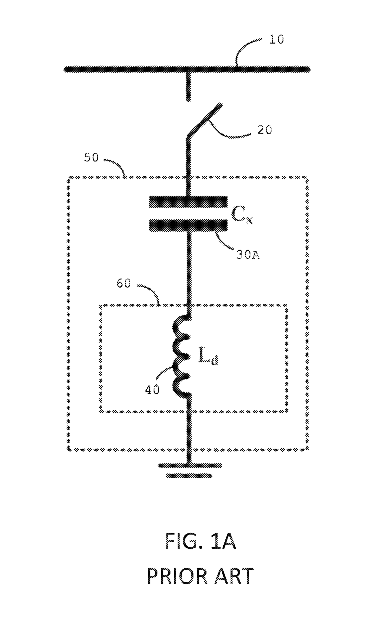
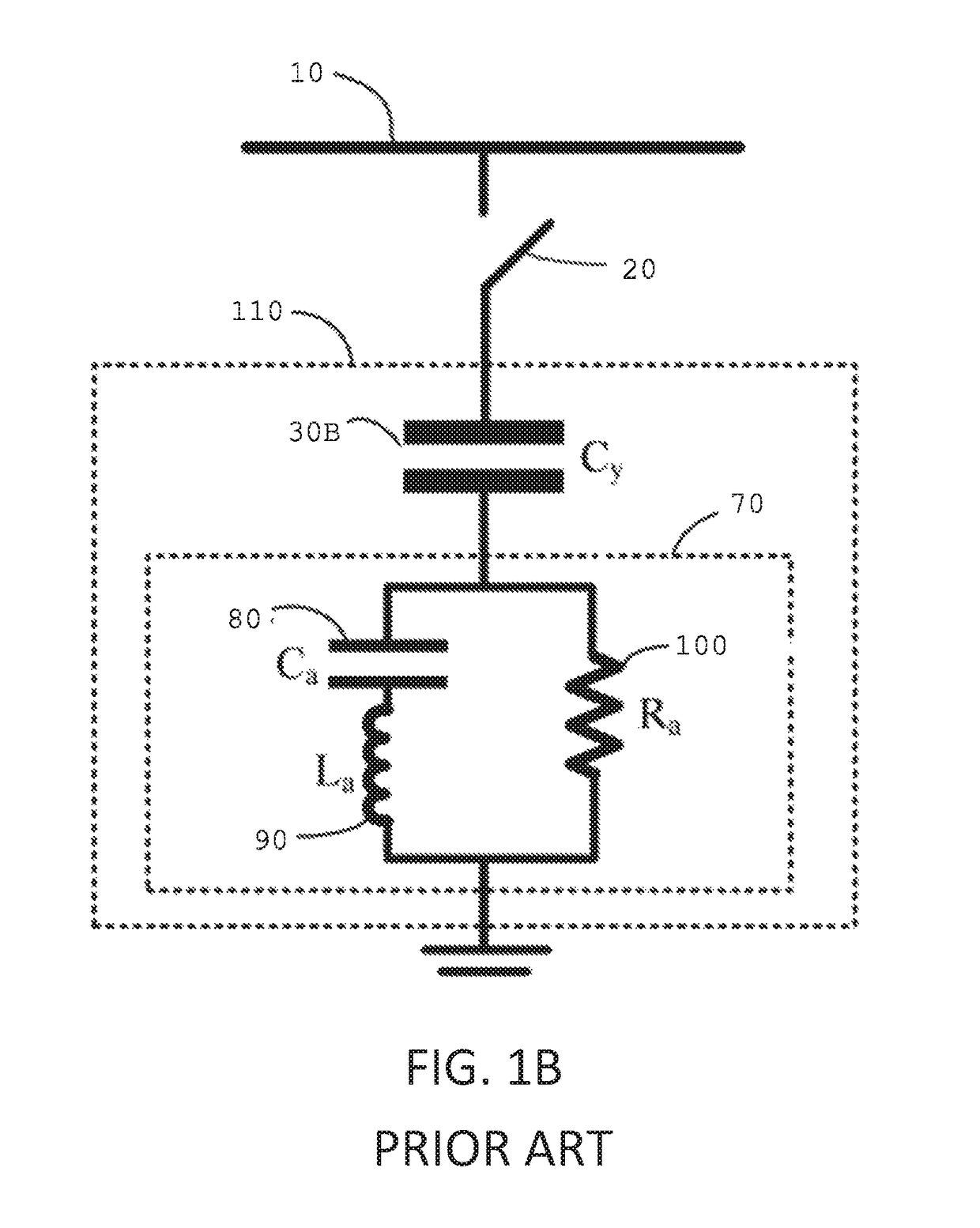
[0026]Referring to FIGS. 1A and 1B, depicted are schemes commonly used for mitigating harmonic resonance of shunt capacitors (all figures shown are in the form of single-phase diagram).

[0027]Referring to FIG. 1A, a bus 10 is coupled to a switch 20. Coupled to the switch 20 is a capacitor 30A.

[0028]Capacitor 30A is coupled in series to inductor 40 which is coupled to ground.

[0029]In the circuit in FIG. 1A, the size of inductor 40 is selected such that subcircuit 50 exhibits an inductive characteristic at frequencies higher than a frequency called the detuning frequency. This frequency can be the fundamental or the 3rd harmonic frequencies. If the system impedance is also inductive, resonance at harmonic frequencies that are higher than the detuning frequency can be avoided. This scheme has been widely used for low voltage (60 is denoted as the detuning element and 40 is the detuning inductor.

[0030]As an alternative to the above, the inductor 40 can be sized to make the total impedanc...


PUM


Abstract

Systems and devices that provide a shared detuning, damping, or filtering element to one or more capacitors. A number of circuit branches are coupled in parallel to each other between a first coupling point and a second coupling point. A subcircuit is coupled between the second coupling point and a third coupling point. Each branch includes at least one capacitor that provides reactive power to power systems while the subcircuit is configured to provide detuning, damping, or filtering to the multiple branches.

Description

TECHNICAL FIELD[0001]The present invention relates to power systems. More specifically, the present invention relates to systems and methods for mitigating the harmonic resonance of capacitors used to provide reactive power to power systems.BACKGROUND[0002]Shunt capacitors are the most commonly used reactive power compensation apparatus in power systems. Connected between a bus and ground, each shunt capacitor injects capacitive reactive power into the system. One or more shunt capacitors can be used to boost the bus voltage, improve the system's power factor, and / or reduce power loss. Since a power system's reactive power needs often change, multiple switchable shunt capacitors can be connected to the same bus. Using switches, each of the capacitors can be connected or unconnected to the system based on system condition. This leads to a variable reactive power compensation apparatus. For example, if there are two switchable capacitors of 1 MVar and 1.5 MVar respectively, the total ...

Claims


Application Information

Patent Timeline
Patent Type & Authority Patents(United States)
IPC IPC(8): H02J3/01H02J3/18
CPCH02J3/01H02J3/18H02J3/1828Y02E40/30Y02E40/40
Inventor WANG, YANGXU, WILSUN
Owner XU WILSUN
Learn More