Rotor for an electric machine, an electric machine and method for manufacturing an electric machine

a technology of electric machines and rotors, which is applied in the direction of machines/engines, magnetic circuit rotating parts, and shape/form/construction of magnetic circuits, etc., and can solve the problems of reducing efficiency and maximum torque, increasing no-, and deteriorating electrical properties of electric machines

Active Publication Date: 2018-04-10
ABB (SCHWEIZ) AG
View PDF17 Cites 2 Cited by
  • Summary
  • Abstract
  • Description
  • Claims
  • Application Information

AI Technical Summary

Benefits of technology

[0008]An exemplary rotor for an electric machine is disclosed, comprising: a rotor core having a plurality of rotor sheets stacked in an axial direction, wherein each of the plurality of rotor sheets having a plurality of flux guide sections located along a circumferential direction of the rotor sheet, wherein each of the plurality of flux guide sections including a plurality of flux paths made of a material of high permeance and a plurality of flux barriers made of a material of low permeance located alternately along a radial direction of the flux guide section, and wherein the plurality of flux guide sections includes: a first flux guide section in which a first number of the plurality of flux barriers has a bridge interrupting the flux barrier; and a second flux guide section in which a second number of the plurality of flux barriers has a bridge interrupting the flux barrier, wherein each of the bridges being made of a material of high permeance, wherein the first number is different than the second number.
[0016]An advantage of the disclosure can be that electrical properties of an electric machine having rotor sheets including bridges crossing flux barriers can be improved without need to reduce width of the bridges. In a way the present disclosure reduces effective width of bridges without need to reduce actual width thereof.

Problems solved by technology

The leak flux decreases efficiency and maximum torque and increases no-load current thereby deteriorating electrical properties of the electric machine.
A problem associated with punching can be that narrow bridges cannot be formed with it.

Method used


Image

  • Rotor for an electric machine, an electric machine and method for manufacturing an electric machine
  • Rotor for an electric machine, an electric machine and method for manufacturing an electric machine
  • Rotor for an electric machine, an electric machine and method for manufacturing an electric machine

Examples


Embodiment Construction

[0014]Exemplary embodiments of the present disclosure improve electrical properties of an electric machine whose rotor sheets include bridges while being obtainable by punching.

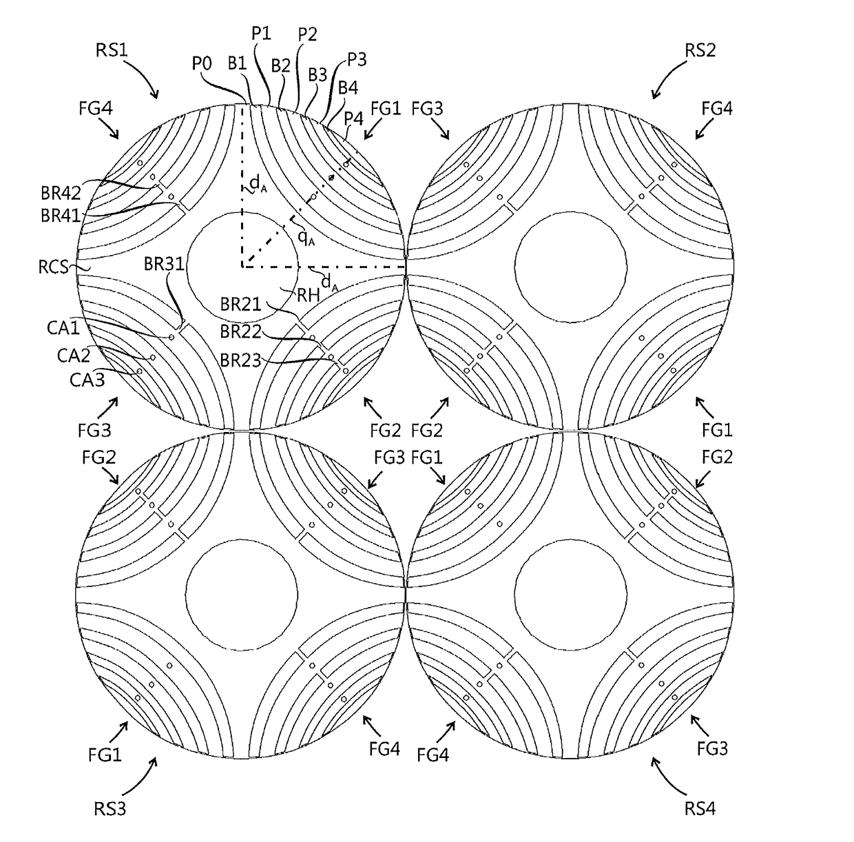
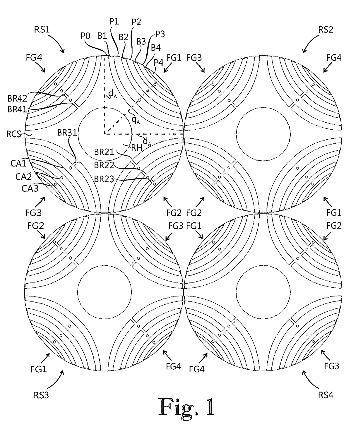
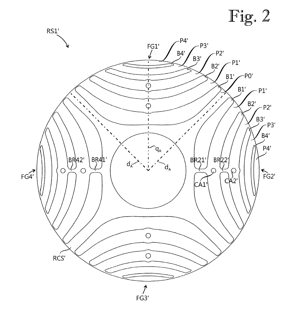
[0015]The exemplary embodiments described herein provide a rotor sheet which includes at least two types of flux guide sections, each said type of flux guide section having a different number of flux barriers with bridges compared with the rest of the types. In a rotor the rotor sheets can be arranged such that adjacent a first type flux guide section in the axial direction there can be a second type flux guide section. Because rotor sheets can be axially pressed against each other, a bridge in a flux barrier of a first flux guide section can also be capable of supporting a flux barrier of a second flux guide section located adjacent the first flux guide section in the axial direction. In an axial series of flux barriers some flux barriers have a bridge and the others do not have a bridge. Therefore an averag...


PUM

PropertyMeasurementUnit
widthaaaaaaaaaa
circumferenceaaaaaaaaaa
angleaaaaaaaaaa

Abstract

A rotor for an electric machine includes a rotor core having a plurality of rotor sheets (RS1), each of the plurality of rotor sheets including a plurality of flux guide sections, each of the plurality of flux guide sections having a plurality of flux paths and a plurality of flux barriers. The plurality of flux guide sections having a first flux guide section in which a first number of the plurality of flux barriers has a bridge interrupting the flux barrier, and a second flux guide section in which a second number of the plurality of flux barriers has a bridge interrupting the flux barrier. Each bridge is made of a material of high permeance, and the first number of the first flux guide section is different than the second number of the second flux guide section.

Description

RELATED APPLICATION(S)[0001]This application claims priority under 35 U.S.C. § 120 to International Application PCT / EP2013 / 076016 which was filed on Dec. 10, 2013, designated the U.S., and claimed priority to European application 12197147.7 filed on Dec. 14, 2012. The content of each prior application is hereby incorporated by reference in its entirety.FIELD[0002]The present disclosure relates to a rotor for an electric machines, to an electric machine including said rotor, and to a method for manufacturing an electric machine.BACKGROUND INFORMATION[0003]In an electric machine rotor provided with a plural number of magnetic poles, arranged substantially at equal intervals along the circumference of the rotor, each magnetic pole can have a direct pole axis, or a direct axis. Two adjacent direct pole axes form an angle that is bisected by a quadrature axis. The reactance corresponding to the direct pole axis can be called a direct-axis reactance and the reactance corresponding to the ...

Claims


Application Information

Patent Timeline
Patent Type & Authority Patents(United States)
IPC IPC(8): F02K1/08H02K15/02H02K1/27H02K1/24
CPCH02K1/246H02K15/022H02K1/2766Y10T29/49012
Inventor KOLEHMAINEN, JERE
Owner ABB (SCHWEIZ) AG
Why Eureka
Try Eureka