
Unmanned aerial vehicle, unmanned aerial vehicle charging system and control method thereof

a technology for unmanned aerial vehicles and charging systems, which is applied in the direction of electric vehicle charging technology, charging stations, transportation and packaging, etc., can solve the problems of limited energy storage capacity, difficult to increase endurance time, and aircraft which perform dangerous missions, so as to ensure the continuity of missions

Active Publication Date: 2018-04-17
IND ACADEMIC COOP FOUND GYEONGSANG NAT UNIV
View PDF4 Cites 6 Cited by
  • Summary
  • Abstract
  • Description
  • Claims
  • Application Information

AI Technical Summary

Benefits of technology

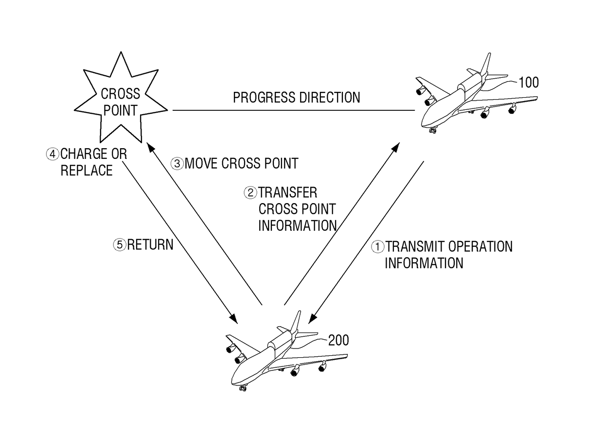
The present invention is about an unmanned aerial vehicle (UAV) that can be charged by a dynamic charging system for long flying sessions. This allows for continuous operation of the UAV for longer periods of time without the need for a human pilot to control it. The technical effects are improved efficiency and reliability of the UAV, as well as reduced costs and improved mission continuity.

Problems solved by technology

The UAV means an airplane which performs a dangerous mission to be difficult to be directly performed by a human or be directly performed by a remote control or an autonomous flight control apparatus without a pilot.
However, since a battery mounted on the UAV is only limited in size and weight, there is a limit to energy storage capacity, and as a result, it is much difficult to increase the endurance time.
However, a charging method by a static charging system has problems in that continuity of the mission capability of the UAV is vitiated and much cost to separately establish the charging system is consumed.

Method used


Image

  • Unmanned aerial vehicle, unmanned aerial vehicle charging system and control method thereof
  • Unmanned aerial vehicle, unmanned aerial vehicle charging system and control method thereof
  • Unmanned aerial vehicle, unmanned aerial vehicle charging system and control method thereof

Examples


Embodiment Construction

[0032]Certain exemplary embodiments of the present invention will now be described in greater detail with reference to the accompanying drawings.

[0033]In the following description, same drawing reference numerals are used for the same elements even in different drawings. The matters defined in the description, such as detailed construction and elements, are provided to assist in a comprehensive understanding of the invention. Thus, it is apparent that the exemplary embodiments of the present invention can be carried out without those specifically defined matters. Also, well-known functions or constructions are not described in detail since they would obscure the invention with unnecessary detail.

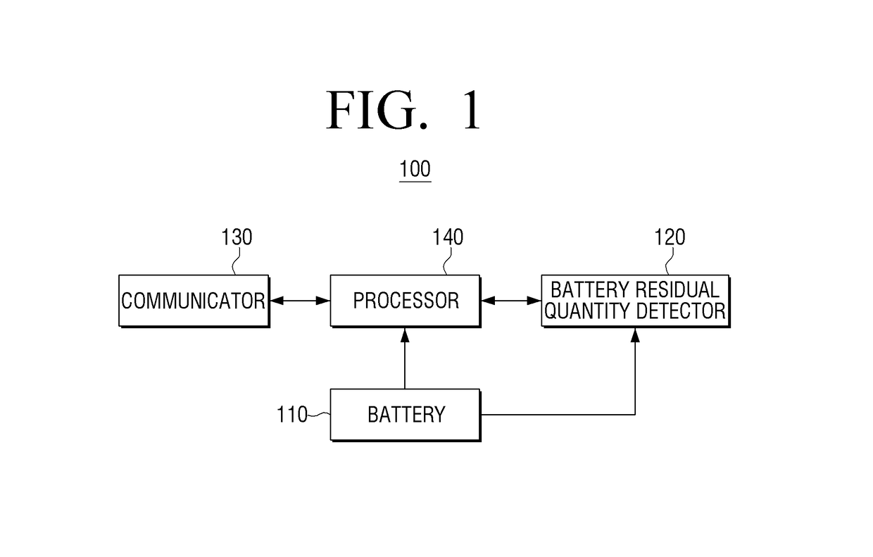
[0034]FIG. 1 is a block diagram schematically illustrating a configuration of an unmanned aerial vehicle according to an exemplary embodiment of the present invention.

[0035]Referring to FIG. 1, an unmanned aerial vehicle 100 according to an exemplary embodiment of the present invention inclu...


PUM


Abstract

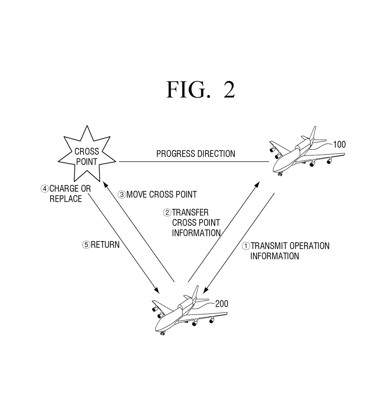
An unmanned aerial vehicle is provided. The unmanned aerial vehicle includes: a battery; a battery residual quantity detector configured to detect a residual quantity of the battery; a communicator configured to perform communication with a rechargeable unmanned aerial vehicle used in charging or replacement of the battery; and a processor configured to control the communicator to transmit its operation information to the rechargeable unmanned aerial vehicle detected within a predetermined distance when the detected residual quantity of the battery is less than the predetermined reference quantity and control to wirelessly charge the battery by the power supplied from the rechargeable unmanned aerial vehicle to maintain an operable state of the unmanned aerial vehicle or replace the battery to a new battery provided from the rechargeable unmanned aerial vehicle when being close to the rechargeable unmanned aerial vehicle receiving the operation information.

Description

CROSS-REFERENCE TO RELATED APPLICATIONS[0001]This application claims priority from Korean Patent Application No. 10-2015-0027347, filed on Feb. 26, 2015, in the Korean Intellectual Property Office, the disclosure of which is incorporated herein by reference in its entirety.BACKGROUND OF THE INVENTION[0002]Field of the Invention[0003]Apparatuses and methods consistent with the present invention relates to an unmanned aerial vehicle, an unmanned aerial vehicle charging system, and a control method thereof, and more particularly, to an unmanned aerial vehicle, an unmanned aerial vehicle charging system, and a control method thereof capable of wirelessly charging or replacing a battery.[0004]Description of the Related Art[0005]Recently, for the purpose of surface observation, weather observation, military reconnaissance and surveillance, and the like, an unmanned aerial vehicle (UAV) has received attention. The UAV means an airplane which performs a dangerous mission to be difficult to ...

Claims


Application Information

Patent Timeline
Patent Type & Authority Patents(United States)
IPC IPC(8): H02J7/00B64C39/02B60L11/18
CPCB60L11/182B64C39/024B64C2201/066B64C2201/042B60L53/12Y02T90/16Y02T10/70Y02T10/7072Y02T90/14B64U50/34B64U50/19B64D45/00B60Y2200/50B64D2045/0085
Inventor KIM, KI-ILLEE, CHUNG-JAEKIM, KYONG-HOON
Owner IND ACADEMIC COOP FOUND GYEONGSANG NAT UNIV
Learn More