Method of forming spring washer blind-holes into a piston for an automobile transmission

a technology of automobile transmission and blind-hole, which is applied in the field of automobile transmission blind-hole forming method of spring washer blind-hole of piston for automobile transmission through forging technology, which can solve the problems of insufficient forging technology, insufficient forging, and insufficient forging operation, so as to achieve sufficient pin endurance, avoid unnecessary load, and improve the effect of forging efficiency

Inactive Publication Date: 2010-11-02
IBARAKI STEEL CENT +1
View PDF10 Cites 0 Cited by
  • Summary
  • Abstract
  • Description
  • Claims
  • Application Information

AI Technical Summary

Benefits of technology

[0027]According to the first aspect of the present invention, the method of forming spring seat blind-holes into a piston for an automobile transmission, after forging the piston body with a flattened surface on which spring seat blind-holes are disposed, a plurality of spring seat blind-holes are formed at an extremely high speed by one stroke (i.e., simultaneously) of an extrusion operation of pins for piercing the spring seat blind-holes. Since the piercing of the spring seat blind-holes is performed, as above, after having flattened an annular region of the piston body where the spring seat blind-holes are formed, unnecessary load will not be burdened on the pins for piercing spring seat blind-holes leading to sufficiently long endurance of the pins. Besides, a plurality of spring seat blind-holes concerned can be accommodated obviously to all of the cases where they are disposed at an equal angular distance; where a part of them are partially disposed at an equal angular distance; and where all of them are disposed at random.
[0028]Further, the piercing of the spring seat blind-holes is performed by a forward extrusion operation with pins for piercing spring seat blind-holes. Therefore, since, naturally by any means using the die, flow of material is prevented out of the site for relief of material in front of the site where spring seat blind-holes are pierced, unnecessary deformation of the piston body into which spring seat blind-holes are formed will not occur.
[0029]According to the second aspect of the present invention, the method of forming spring seat blind-holes into a piston for an automobile transmission, the annular region along the back side peripheral edge of the end plate of the piston body can be flattened during forging of the piston body of a piston for an automobile transmission without requiring a particular process for the flattening. Moreover, it is convenient that the process of forging the piston body is not especially complicated, but a process which can be simply performed. Although there are many processes except the process above for flattening the region, flattening by the process mentioned above is extremely efficient because the flattening process is completed during the process of a simple forging operation on the piston body.
[0030]According to the third aspect of the present invention, the method of forming spring seat blind-holes into a piston for an automobile transmission, the forward extrusion operation with pins for piercing spring seat blind-holes is performed through guide holes in the lower die while pressing the upper and lower surface of the piston body with an upper die and a lower die and also through making material move away through recess holes bored in the upper die at the corresponding locations of the guide holes. Consequently, formation of spring seat blind-holes can be well performed by allowing excess material to flow and project into the recess holes, and by preventing unnecessary deformation of the piston body due to flow of the material into the other site.
[0031]According to the fourth aspect of the present invention, the method of forming spring seat blind-holes into a piston for an automobile transmission, when the spring seat blind-holes are formed by an upwardly forward extrusion operation with pins for piercing spring seat blind-holes while pressing the upper and lower surface of the piston body with an upper die and a lower die upward, material flowing due to the extrusion operation of pins for piercing spring seat blind-holes can be surely prevented from flowing to protrude down into the lower die by applying upward cushion pressure to the lower die in the same direction as that of the extrusion concerned.
[0032]According to the fifth aspect of the present invention, the method of forming spring seat blind-holes into a piston for an automobile transmission, through confining the sectional area of every recess hole formed in the upper die to an appropriate one, generation of a cavity at the bottom end of the spring seat blind-holes formed can be prevented by means of appropriately restraining flow of the material during forward extrusion operation with the pins for piercing the spring seat blind-holes. That is to say, a problem in that the shape of the bottom end of the spring seat blind-holes formed may become uneven can be solved. In other words, a problem in that the cavity at the bottom end will turn to an opening when a projection, for example, of the material projected opposite to the open end of the spring seat blind-holes is removed can be avoided.

Problems solved by technology

At the moment, it seems that a method of forming spring washer blind-holes of a piston for an automobile transmission through forging technology has not been proposed yet.
The operations above are very inefficient, and moreover, subsequent endmilling operations in the same number as the drilling operations are also necessary and more inefficient in cost.
However, the proposal has not solved such inefficiency that extra parts should be employed and that drilling operations should be repeated as many times as the number of spring seat blind-holes to be required.
When trying to form the holes by drilling, and where the spring seat blind-holes are bored on the end plates of pistons for automobile transmissions, shear stress due to drilling will occur at the tip of a drill, and it is liable to result in occurrence of strain cavities or cracks on the bottom end because of the thin bottom end.

Method used


Image

  • Method of forming spring washer blind-holes into a piston for an automobile transmission
  • Method of forming spring washer blind-holes into a piston for an automobile transmission
  • Method of forming spring washer blind-holes into a piston for an automobile transmission

Examples


Embodiment Construction

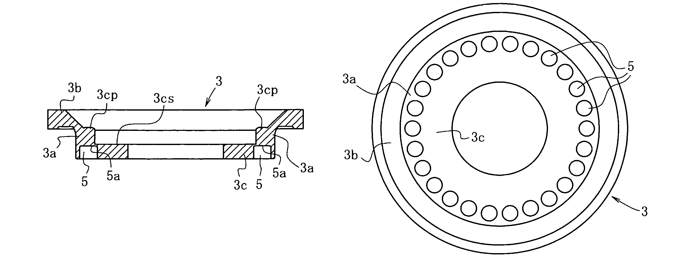
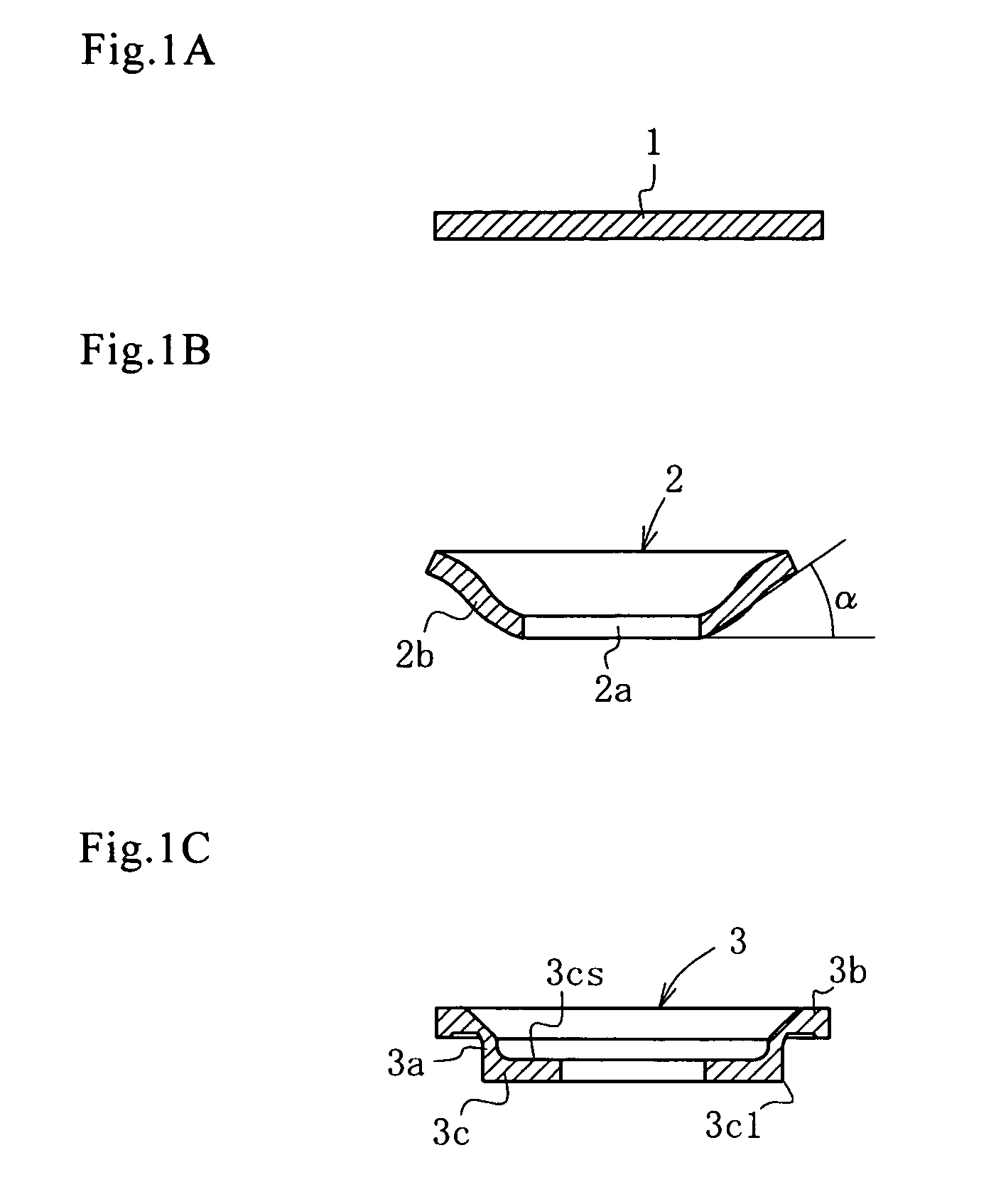
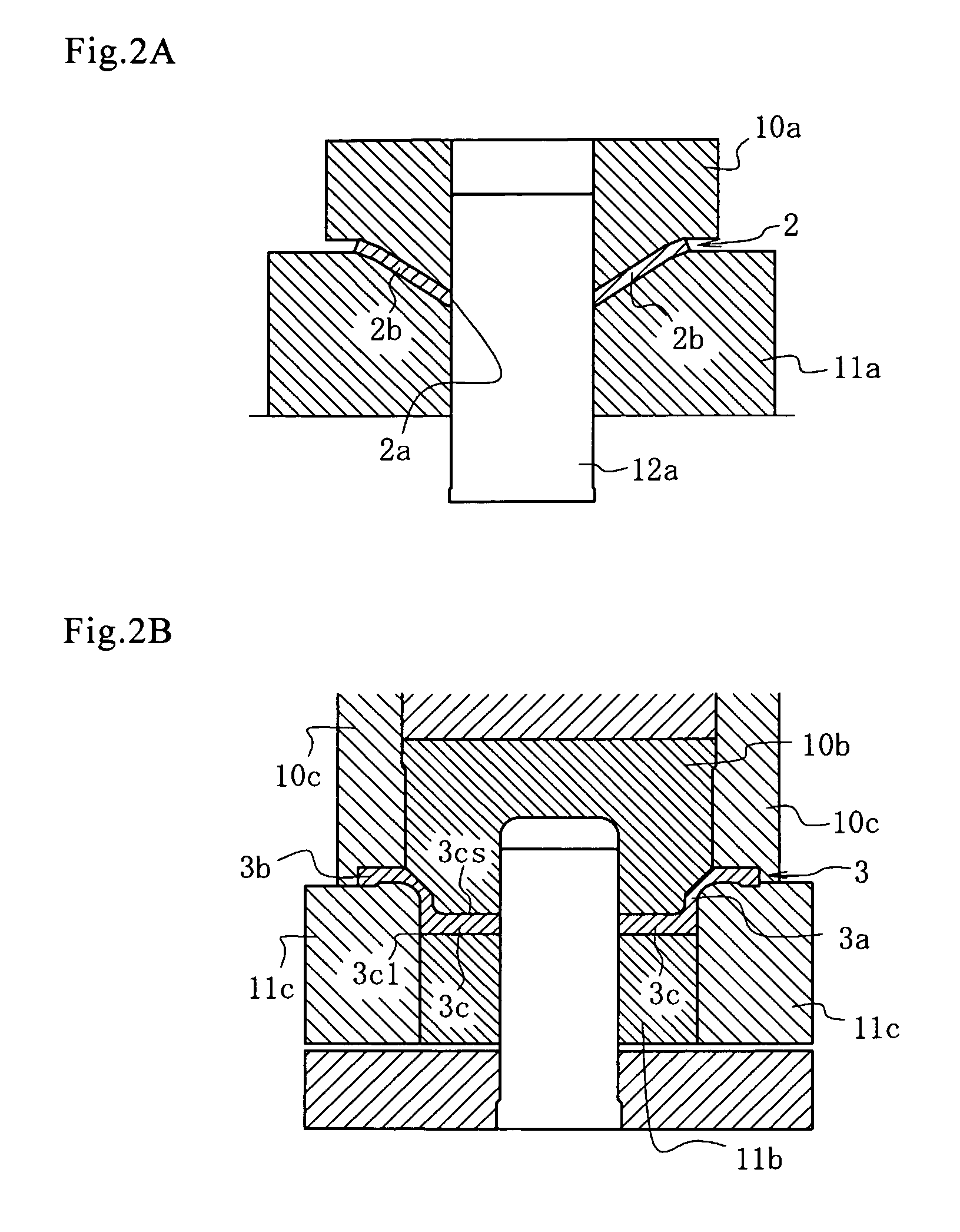
[0020]A second aspect of the present invention is the method of forming spring seat blind-holes into a piston for an automobile transmission according to the first aspect of the present invention, wherein an annular region, on which the plurality of spring seat blind-holes will be formed, along the peripheral edge portion on the back of the end plate of the piston body is flattened. This method further comprises: punching a center hole in the center of a metallic sheet material and simultaneously deep-drawing the circumference of the sheet to make circumferential sidewall rise oblique; making the circumferential sidewall upright; increasing the thickness of the peripheral edge portion on the back of the end plate through flattening part of the end plate locating inside the circumferential sidewall; and further thickening the vicinity of the peripheral edge portion on the back of the end plate and establishing perpendicularity of the surface concerned to the outer surface of the peri...


PUM

PropertyMeasurementUnit
outer diameteraaaaaaaaaa
angleaaaaaaaaaa
anglesaaaaaaaaaa

Abstract

The problem to be solved by the present invention is to clear up an eccentric load onto a pin and a problem of deformation and cavity due to flowing material during extrusion when spring washer blind-holes in a piston for an automobile transmission are formed by extrusion with a pin. After an annular region along the peripheral edge portion on the back of an end plate of a secondary workpiece is flattened, the secondary workpiece is set on a lower die. Further, while the lower die is pressed with upper dies and cushion pressure is applied on the lower die, pins, for piercing the spring washer blind-holes are made to perform an extrusion operation onto the end plate of the secondary workpiece from the backside of the end plate. The extruded material is made to flow into recess holes of the upper die, and thus spring washer blind-holes are formed. Then, projections which have flowed and protrude on the front side are removed by turning with a lathe.

Description

BACKGROUND OF THE INVENTION[0001]1. Technical Field[0002]The present invention relates to a method of forming spring washer (seat) blind-holes of a piston for an automobile transmission, wherein a plurality of spring washer blind-holes on the back of an end plate of the piston for the automobile transmission are formed efficiently, keeping endurance of pins for piercing the spring washer blind-holes, and precisely by cold forging.[0003]2. Background Art[0004]At the moment, it seems that a method of forming spring washer blind-holes of a piston for an automobile transmission through forging technology has not been proposed yet.[0005]For example, it is shown in Patent Document 1 that spring washer blind-holes (they are simply referred to as recesses in the document) are disposed on the inner surface of the end plate of the piston in a multiple-disc clutch. However, there is no comment upon the method of forming them.[0006]With regard to the method of manufacturing oil hydraulic machin...

Claims


Application Information

Patent Timeline
Patent Type & Authority Patents(United States)
IPC IPC(8): B21D22/00B21C23/00
CPCB21J5/02B21K1/18B21K1/32B21K23/00
Inventor OOKA, MASAKAZUHIYAMA, YOSHIKITANABE, KENTAROKANZAKI, YOSHIYUKISATO, SATOSHIYAMAZAKI, YOSHIHISAGOTO, KIICHIRO
Owner IBARAKI STEEL CENT
Why Eureka
Try Eureka