Cover mounting unit

a technology for mounting units and covers, applied in the direction of nuts, bolts, sheet joining, etc., can solve the problems of insufficient thickness of flanges, inability to produce grooves with sheet-metal covers, and substantially restricted access to covers or screws. , to achieve the effect of mainly reducing accessibility

Inactive Publication Date: 2018-04-24
FEDERAL MOGUL SEALING SYST
View PDF14 Cites 0 Cited by
  • Summary
  • Abstract
  • Description
  • Claims
  • Application Information

AI Technical Summary

Benefits of technology

[0053]Depending on design, these centring bodies can assume a pure guiding task without clamping or, depending on design, build up minor to stronger clamping forces which fix the screw in its position also in axial direction. Because of this, each screw can be set to the desired axial position. This can perhaps have major advantages during manual assembly in the event of a repair. In the event of a repair, the accessibility is mostly rendered substantially more difficult compared to the initial assembly, during which the cover is possibly assembled even before the transmission assembly.

Problems solved by technology

For this reason, the accessibility to the cover or to the screws can be substantially restricted in these cases.
However, there are also systems of plastic which are not decoupled that include the preassembled screws.
In the case of thin covers the flange thickness is not adequate in order to preassemble the screw-sleeve concepts.
Grooves cannot be produced with sheet-metal covers.
Protruding screws however would force tightening all screws substantially at the same time.
In the case of cramped assembly conditions, this is not possible as a rule.
Slanting screws however could damage the threads on screwing-in.
However, in the case of conventional thin-walled covers such a fixing of the screw axis is not possible.
The screw connection positions in each case are exactly fixed, since the screws as a rule are not accessible or not sufficiently easily so.
This embodiment makes it possible to mould on the fixing element directly with the moulding-on of the elastomer sealing lip of the carrier frame gasket, which reduces the number of operations and thus the manufacturing costs.
In the event of a repair, the accessibility is mostly rendered substantially more difficult compared to the initial assembly, during which the cover is possibly assembled even before the transmission assembly.

Method used


Image

  • Cover mounting unit
  • Cover mounting unit
  • Cover mounting unit

Examples


Embodiment Construction

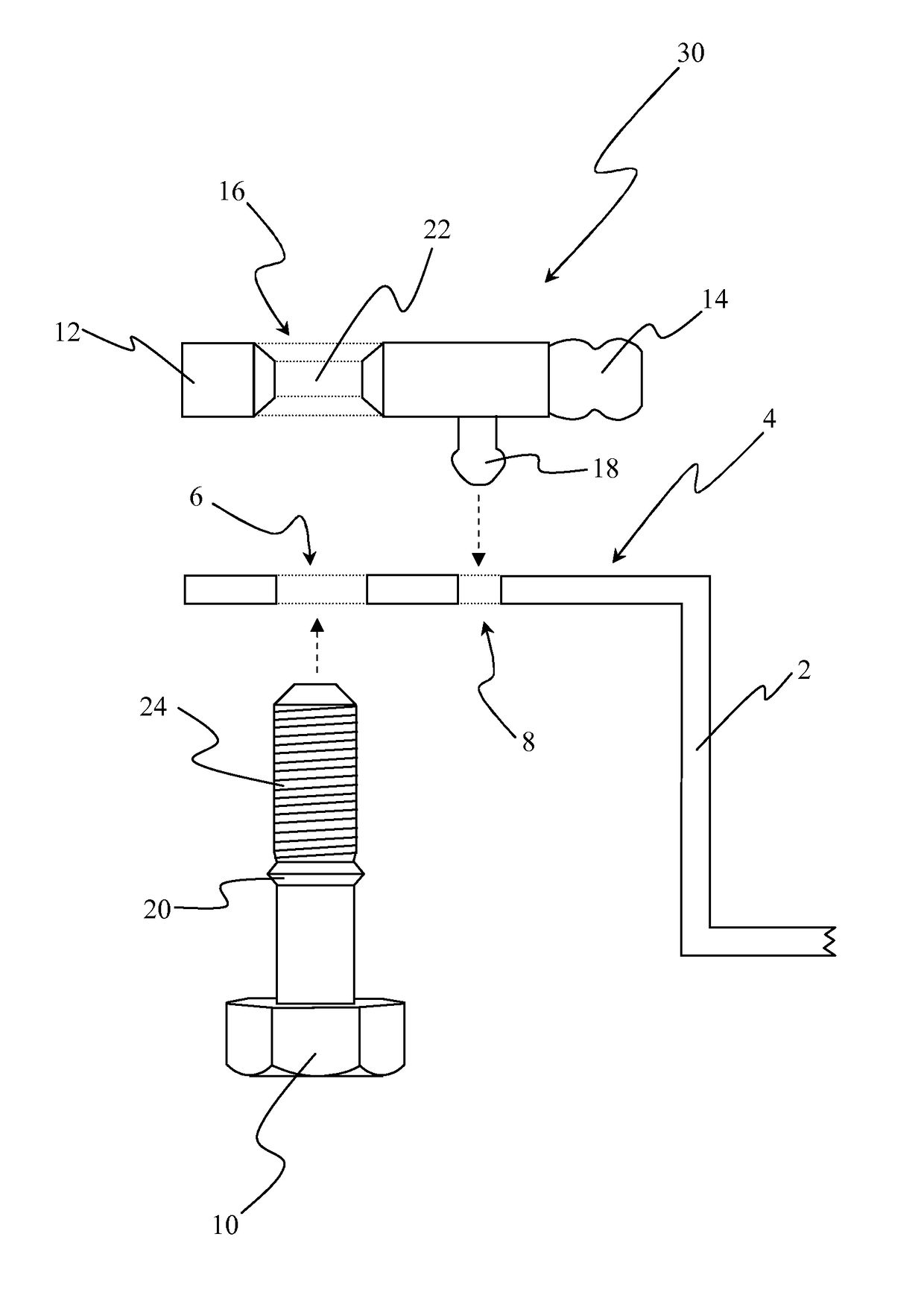
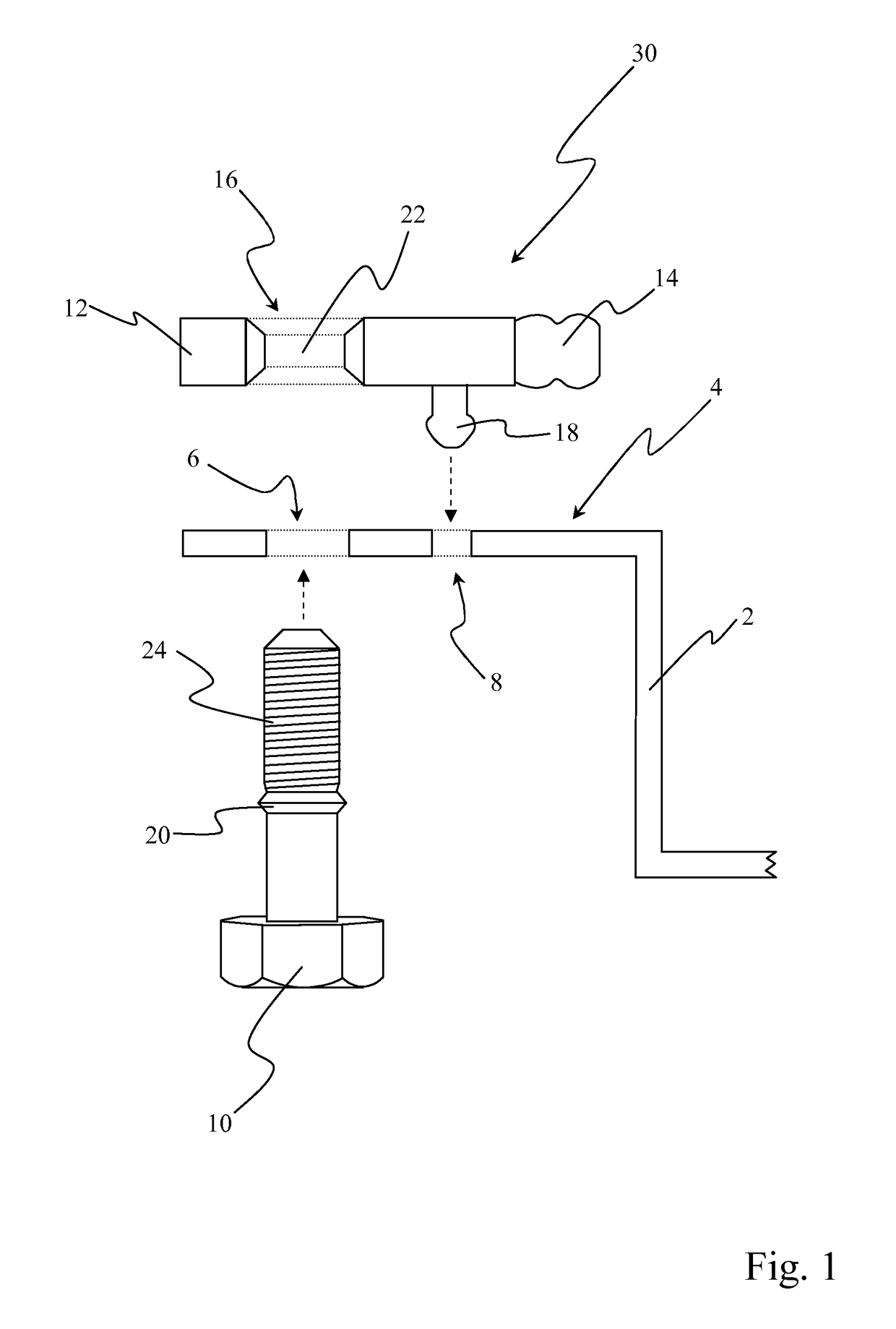
[0062]In FIG. 1, elements of an assembly unit are shown in cross section, in the state before the preassembly takes place. The medium side, i.e. for example engine or gear oil when using the cover as oil pan, is located on the right in this Figure.

[0063]A thin-walled cover pan 2 comprises at least two screw holes 6 (only one is shown here), and at least one fixing opening 8. The fixing opening 8 in this case is shown as a continuous hole, but can also be a blind hole in alternative embodiments. The cover pan 2 comprises a sealing flange 4.

[0064]A carrier frame gasket 30 comprises a carrier frame 12 and a gasket 14 for sealing on the sealing flange 4 of the cover pan 2. The carrier frame gasket 30 comprises a screw passage 16 (only one is shown here) for each screw hole of the cover pan 2. In the screw passage 16, a centring body is arranged. The carrier frame gasket 30 furthermore comprises a fixing element 18 for each fixing opening 8 in the cover pan 2.

[0065]In this embodiment, no...


PUM


Abstract

A cover assembly unit includes a thin-walled cover pan with a sealing flange, at least two screw holes in the sealing flange, at least one fixing opening, a fastening screw captively arranged in each screw hole; and a carrier frame gasket with a carrier, a gasket, which bears against the sealing flange, a screw passage for each screw hole, a fixing element for each fixing opening, and a centering body for the fastening screw in each screw passage.

Description

BACKGROUND1. Technical Field[0001]The present invention relates to a cover assembly unit, in particular for the automobile sector. Such cover assembly units can be used for example as cylinder head covers, oil pan or transmission covers. The cover assembly unit comprises a particularly thin-walled cover pan, a gasket and two or more fastening screws.2. Related Art[0002]In particular in the automobile sector, there are many housing parts on the engine or transmission that are closed with various covers. These covers are for example cylinder head covers or oil pan gaskets, as these are used with engines or transmissions. In most systems on engines known to date it is usual that the oil pan is arranged positioned horizontally under the engine. This means that the oil pan and also the oil pan screws are easily accessible during all maintenance operations. This arrangement is also evident in principle with the usual transmission designs.[0003]In the case of later transmission concepts, s...

Claims


Application Information

Patent Timeline
Patent Type & Authority Patents(United States)
IPC IPC(8): F02B77/04F01M11/00F16B5/02F16B5/06F16B41/00F16J15/06
CPCF01M11/0004F16B5/0208F16J15/061F16B5/0664F16B41/002F16B5/0642
Inventor SALAMEH, RALF
Owner FEDERAL MOGUL SEALING SYST
Why Eureka
Try Eureka