Mortarless stone veneer

a technology of stone veneer and mortar, applied in the field ofmortarless stone veneer, can solve the problem of not intended summary

Active Publication Date: 2018-05-01
COLLISON RYAN W
View PDF9 Cites 9 Cited by
  • Summary
  • Abstract
  • Description
  • Claims
  • Application Information

AI Technical Summary

Benefits of technology

[0003]This Summary is provided to introduce a selection of concepts in a simplified form that are further described below in the Detailed Description. This Summary is not intended to identify key aspects or essential aspects of the claimed subject matter. Moreover, this Summary is not intended for use as an aid in determining the scope of the claimed subject matter.

Problems solved by technology

Moreover, this Summary is not intended for use as an aid in determining the scope of the claimed subject matter.

Method used


Image

  • Mortarless stone veneer
  • Mortarless stone veneer
  • Mortarless stone veneer

Examples


Embodiment Construction

[0014]Embodiments are described more fully below with reference to the accompanying figures, which form a part hereof and show, by way of illustration, specific exemplary embodiments. These embodiments are disclosed in sufficient detail to enable those skilled in the art to practice the invention. However, embodiments may be implemented in many different forms and should not be construed as being limited to the embodiments set forth herein. The following detailed description is, therefore, not to be taken in a limiting sense in that the scope of the present invention is defined only by the appended claims.

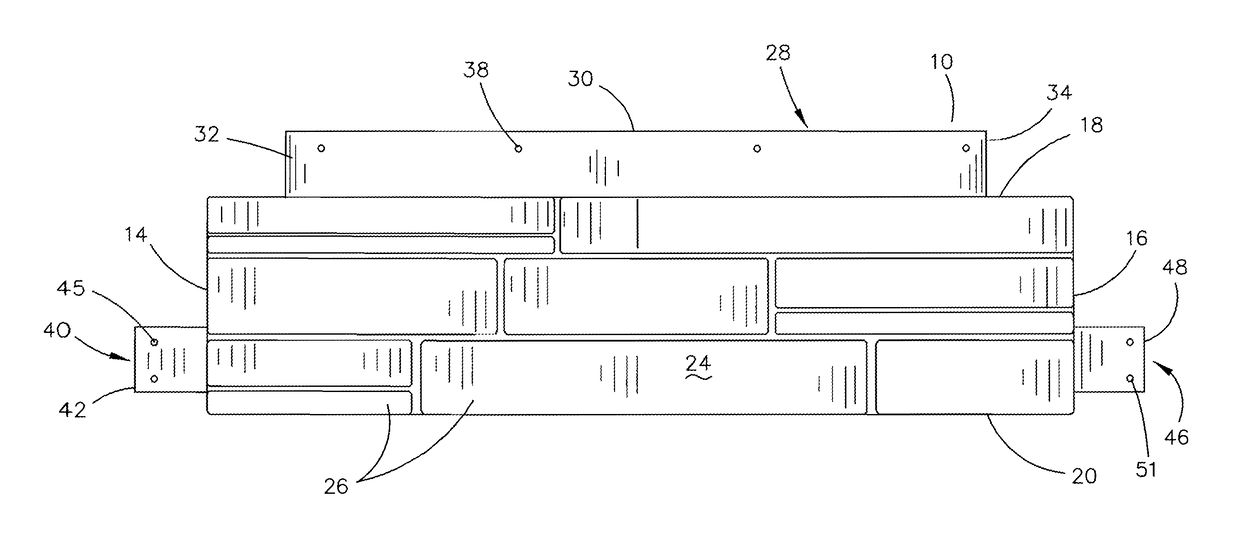
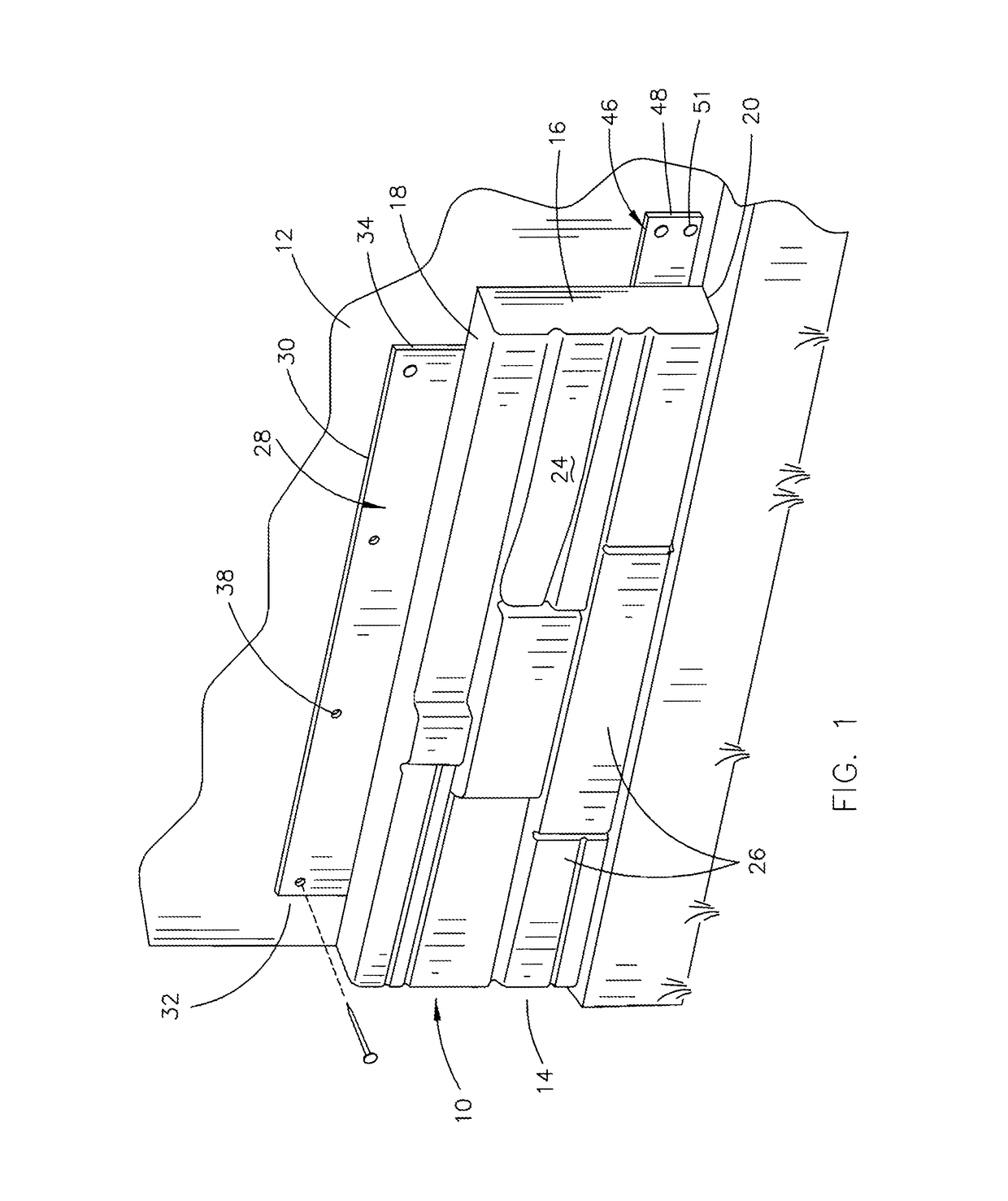
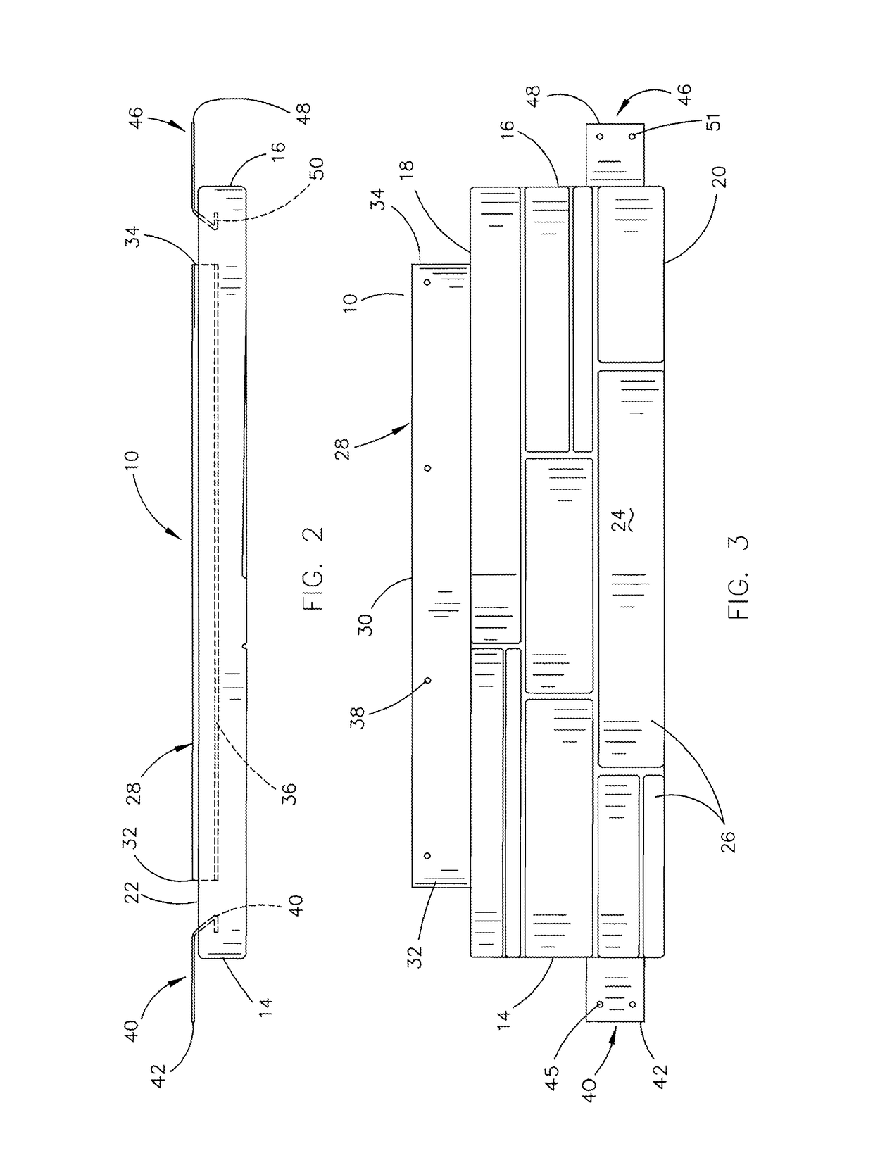
[0015]The mortarless stone veneer of this invention is designated by the reference numeral 10 and is shown in a panel format. For purposes of concise description, the mortarless stone veneer 10 will be described as panel 10. Panel 10 is comprised of concrete or lightweight concrete. Panel 10 may be used on the exterior of a building 12 or on a wall in the interior of a building.

[00...


PUM


Abstract

A mortarless stone veneer is provided which is in a panel format and which has an upper end, a lower end, a first end, a second end, a front side and a rear side. An upper attachment flange has its lower end embedded in the rear side of the panel so as to extend upwardly therefrom. A first end attachment flange has its inner end embedded in the panel at the first end thereof. A second end attachment flange has its inner end embedded in the panel at the second end. The end attachment flanges are bendably movable between an extended attachment position and a folded position behind the panel.

Description

BACKGROUND OF THE INVENTIONField of the Invention[0001]This invention relates to a mortarless stone veneer and more particularly to a mortarless stone veneer which is comprised of a concrete panel having an upper attachment flange, a first end attachment flange and a second end attachment flange.Description of the Related Art[0002]The Assignee of this invention has been marketing a mortarless stone veneer for some time wherein the product included a panel which had an attachment flange extending upwardly from the upper end of the panel. Although Assignee's prior product has met with success, Assignee has discovered that there are times when end attachment flanges will stabilize the panel when mounted on a vertically disposed support such as a wall or the like. Further, in Assignee's prior product, there was little thereon to permit some air flow between the panel and the supporting wall to reduce moisture buildup on the wall.SUMMARY OF THE INVENTION[0003]This Summary is provided to ...

Claims


Application Information

Patent Timeline
Patent Type & Authority Patents(United States)
IPC IPC(8): E04F13/07E04F13/14E04F13/08
CPCE04F13/147E04F13/0839E04F13/07E04F13/0835E04F13/0862
Inventor COLLISON, RYAN W.
Owner COLLISON RYAN W
Why Eureka
Try Eureka