Motor and winding assembly thereof

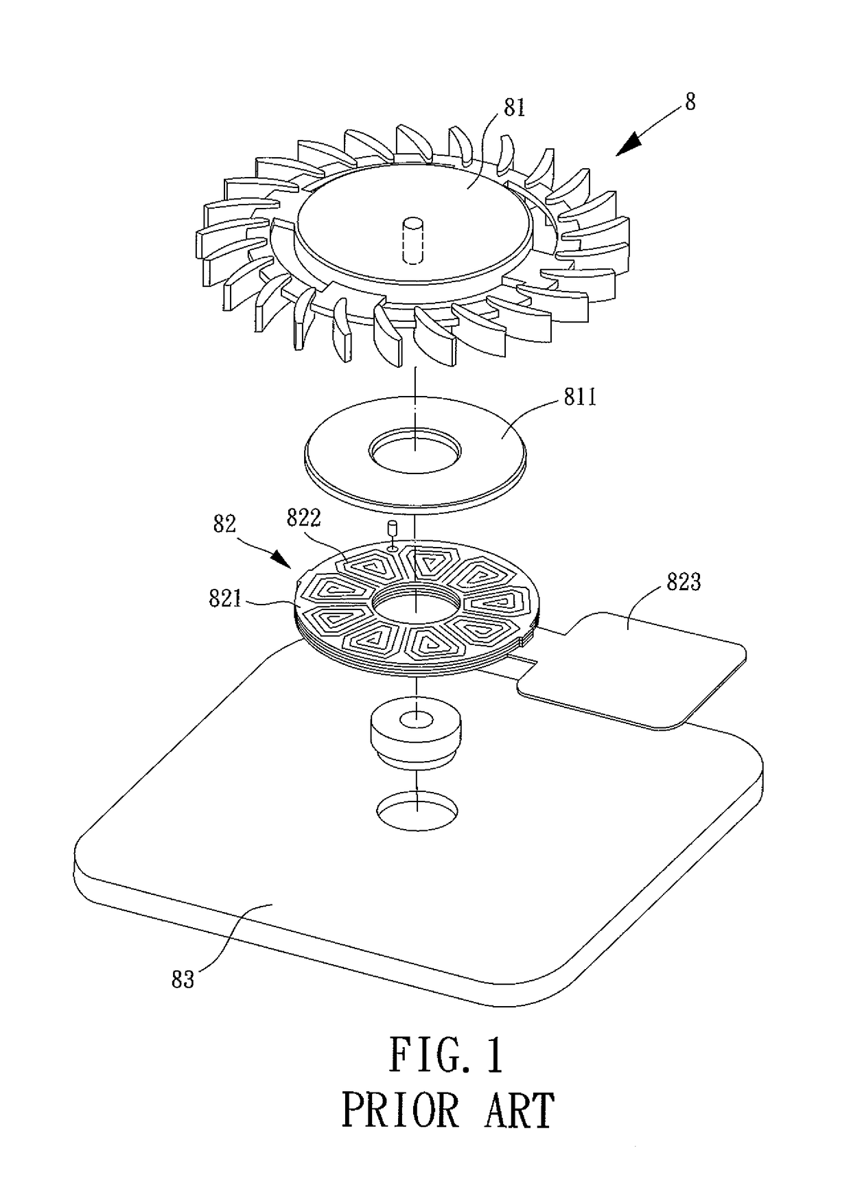
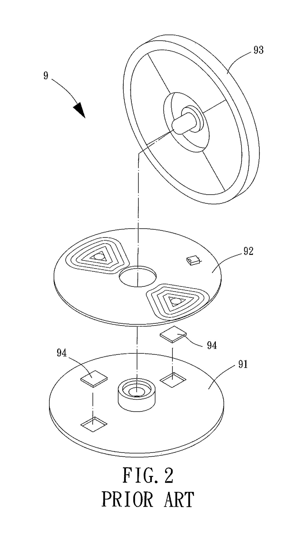
a technology of motor and winding assembly, which is applied in the direction of dynamo-electric machines, structural associations, supports/encloses/casings, etc., can solve the problems of inconvenient assembly, complicated assembly of the motor b>9/b>, and adversely affecting the miniaturization of the conventional motor, so as to achieve the effect of reducing the radial width of the motor and simplifying the assembly of the motor

Active Publication Date: 2018-05-01
SUNONWEALTH ELECTRIC MACHINE IND
View PDF20 Cites 2 Cited by
  • Summary
  • Abstract
  • Description
  • Claims
  • Application Information

AI Technical Summary

Benefits of technology

[0009]It is therefore the objective of this invention to provide a motor whose radial width is effectively reduced.
[0010]It is another objective of this invention to provide a motor with an improved and convenient assembly procedure.
[0020]Due to the arrangement of the folding portion of the winding assembly, the circuit supporting portion can be folded and stacked with the coil supporting portion(s). Thus, the radial width of the motor is efficiently reduced, and the assembly of the motor is simplified. Therefore, miniaturization of the motor of the present invention and convenient assembly of said motor can be provided.

Problems solved by technology

Therefore, a radial width of the motor is increased, thus adversely affecting the miniaturization of the conventional motor 8.
Thus, the assembly of the motor 9 is complicated and inconvenient.

Method used


Image

  • Motor and winding assembly thereof
  • Motor and winding assembly thereof
  • Motor and winding assembly thereof

Examples


Embodiment Construction

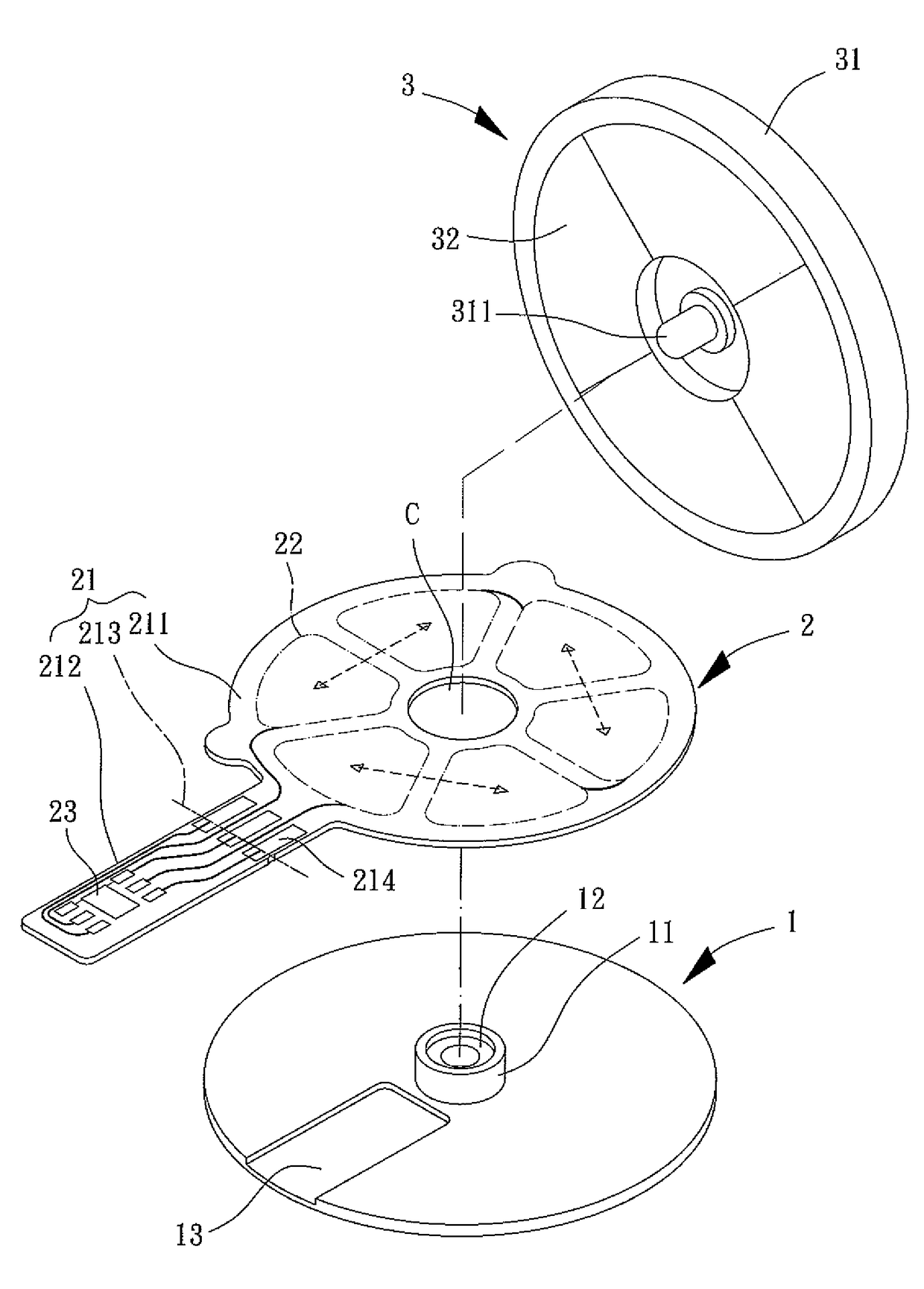
[0031]Please refer to FIG. 3, a motor according to a first embodiment of the present invention includes a base 1, a winding assembly 2 and a rotor 3. The base 1 may be coupled with the winding assembly 2, and the rotor 3 is rotatably coupled to the base 1. The winding assembly 2 is used to drive the rotor 3 to rotate.

[0032]A pivoting portion 11 is arranged on one surface of the base 1 and can be in the form of a shaft tube, a shaft seat or other structure with which the rotor 3 can be rotatably coupled. In this embodiment, the pivoting portion 11 is a shaft tube, and a bearing 12 may be received in the shaft tube.

[0033]The winding assembly 2 includes a support 21. The support 21 can be a flexible printed circuit board, a flexible substrate or other foldable plate, which is not limited in the present invention. The support 21 includes at least one coil supporting portion 211 and a circuit supporting portion 212 connected to the at least one coil supporting portion 211. A central hole...


PUM


Abstract

A motor includes a base, a winding assembly and a rotor. The base includes a pivoting portion. The winding assembly includes a support. The support includes at least one coil supporting portion and a circuit supporting portion connected to the at least one coil supporting portion. A coil is arranged on each of the at least one coil supporting portion. A circuit is arranged on the circuit supporting portion and electrically connected to the coil or coils. A folding portion is arranged between the at least one coil supporting portion and the circuit supporting portion. The circuit supporting portion and the at least one coil supporting portion are folded and stacked together via the folding portion. The rotor is rotatably coupled to the pivoting portion of the base. Due to the arrangement of the folding portion, a radial width of the motor is efficiently reduced.

Description

CROSS REFERENCE TO RELATED APPLICATIONS[0001]The application claims the benefit of Taiwan application serial No. 103137879, filed on Oct. 31, 2014, the subject matter of which is incorporated herein by reference.BACKGROUND OF THE INVENTION[0002]1. Field of the Invention[0003]The present invention generally relates to a motor and a winding assembly thereof and, more particularly, to a motor having a foldable winding assembly.[0004]2. Description of the Related Art[0005]Please refer to FIG. 1, a conventional motor 8 includes a rotor 81 and a foldable stator 82. A permanent magnet 811 of the rotor 81 is magnetically linked with the foldable stator 82, driving the rotor 81 to rotate. The foldable stator 82 includes a plurality of supports 821 stacked together to form a foldable support structure. A coil 822 is arranged on each of the supports 821. In addition, a driving circuit 823 is electrically connected to a side of the foldable stator 82. Detailed structure and operational principl...

Claims


Application Information

Patent Timeline
Patent Type & Authority Patents(United States)
IPC IPC(8): H02K3/26H02K5/22H02K11/00H02K11/30
CPCH02K5/225H02K11/30H02K3/26H02K2211/03H02K11/33
Inventor CHEN, GUAN-MINGLIN, CHANG-YULYU, LI-YANG
Owner SUNONWEALTH ELECTRIC MACHINE IND
Why Eureka
Try Eureka