Support for tensioned screening media

a technology of capping and tensioning media, which is applied in the direction of screening, solid separation, chemistry apparatus and processes, etc., can solve the problems of increasing the abrasion contact between the capping and the media, affecting the abrasion resistance of the capping, and the capping is disadvantageous, so as to facilitate the entrapment of stones, facilitate mounting, and effectively close the open structure or aperture

Active Publication Date: 2018-05-08
SANDVIK INTELLECTUAL PROPERTY AB
View PDF11 Cites 1 Cited by
  • Summary
  • Abstract
  • Description
  • Claims
  • Application Information

AI Technical Summary

Benefits of technology

[0008]It is an objective of the present invention to provide screening apparatus and in particular a capping for a screening media support beam that is configured to support tensioned screening media having an open structure or apertures that extend continuously along the length of the screening media between its lengthwise ends (positioned at the sidewalls of the screen deck). It is a further specific objective to provide a support capping that does not facilitate entrapment of stones or gravel between the capping and the screening media during use. It is a yet further objective to provide a capping that facilitates mounting of cross-tensioned, length-tensioned or pre-tensioned screening mediate to create a crowned or humped-shaped screen deck that is effective to ‘blind’ the media from below so as to effectively close the open structure or apertures at the region of each capping.
[0009]The objectives are achieved by providing a capping having arms configured to clamp onto the media support beam and a head configured to support an underside surface of the screening media where the head is flexible so as to provide and maintain close-touching contact with the underside surface of the media to effectively ‘close’ the open mesh or apertures of the media at its underside surface. In particular, the head of the capping is separated from the arms by a neck such that the head comprises laterally outward extending flanges that are configured to flex and compress downwardly towards the arms when positioned to support the media from below. When in the supporting configuration, in contact with the underside surface of the media, a media contact surface of the head is arranged to be substantially co-planar with the media underside surface and in particular not to curve or be declined downwardly away from the media underside surface that would otherwise create pockets between the media surface and the head for entrapment of stones and gravel.
[0011]Preferably, the head comprises a media contact surface that extends over the flanges, the contact surface being generally concave in a lateral widthwise direction of the head between respective endmost edges of the flanges. Optionally, the contact surface may be considered to be inclined over each flange in a lateral widthwise direction of the head relative to a central region positioned over the neck. Such an arrangement is advantageous to provide complete contact between the surface of the capping head and the underside surface of the media to completely close or blind the media open structure or apertures at a region directly above the capping. Stones and gravel are accordingly prevented from being entrapped at the region of each capping.
[0013]Preferably, the flanges are separated from the arms in a height direction of the capping by a length of the neck in the height direction and a shoulder region of each arm at a junction with the neck is declined to slope downwardly away from each respective flange. The downwardly sloping shoulders of the upper ends of arm increase the range of available flex of each flange to provide appropriate cushioning of the media during use. Preferably, a thickness of each flange in a height direction of the capping increases in a lateral widthwise direction of the head such that widthwise outer regions of the flanges are thicker than corresponding widthwise inner regions of the flanges that form a junction with the neck. Such an arrangement is convenient for manufacture and provides the concave or laterally raised shaped profile of the media contact surface of the head without compromising the integrity of the capping.
[0015]Preferably, the capping comprises a flexible material such that the flanges are resiliently compressible towards the arms. Preferably, the fingers are resiliently compressible towards each respective arm. Accordingly, the fingers and flanges are configured to bend when positioned in contact with the carrier beam and media, respectively and to return to their non-flexed configuration when the capping is either detached from the carrier beam or the media. Preferably, the arms are resiliently expandable to open the channel to receive and mount the capping. The flexible fingers and / or arms are advantageous to provide a universal capping suitable for mounting upon support beams of different dimensions and geometries. Optionally, the capping is formed as a moulded single unitary body and comprises a rubber or a polyurethane material.

Problems solved by technology

Modular screen decks are disadvantageous as the modular panels are manufacturer specific and are therefore higher cost and not as accessible as tensioned screening media.
However, where the media comprises a continuously open structure along its length, it is common for stones or gravel to become lodged between the media and the cappings which both affects how the media sits upon the deck frame (by changing its orientation angle) and significantly increases the abrasion contact between the capping and the media to accelerate wear.
However, alignment of the ‘blinds’ with the cappings is not always optimised and also such non-standardised media tends to be higher cost and not as accessible.

Method used


Image

  • Support for tensioned screening media
  • Support for tensioned screening media
  • Support for tensioned screening media

Examples


Embodiment Construction

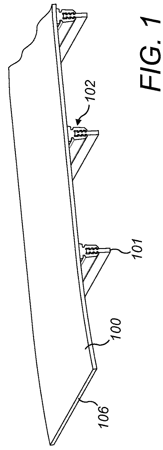
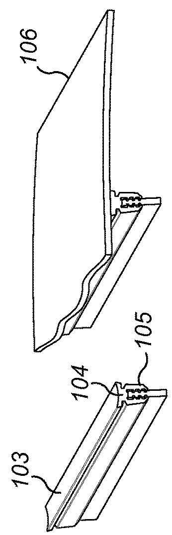
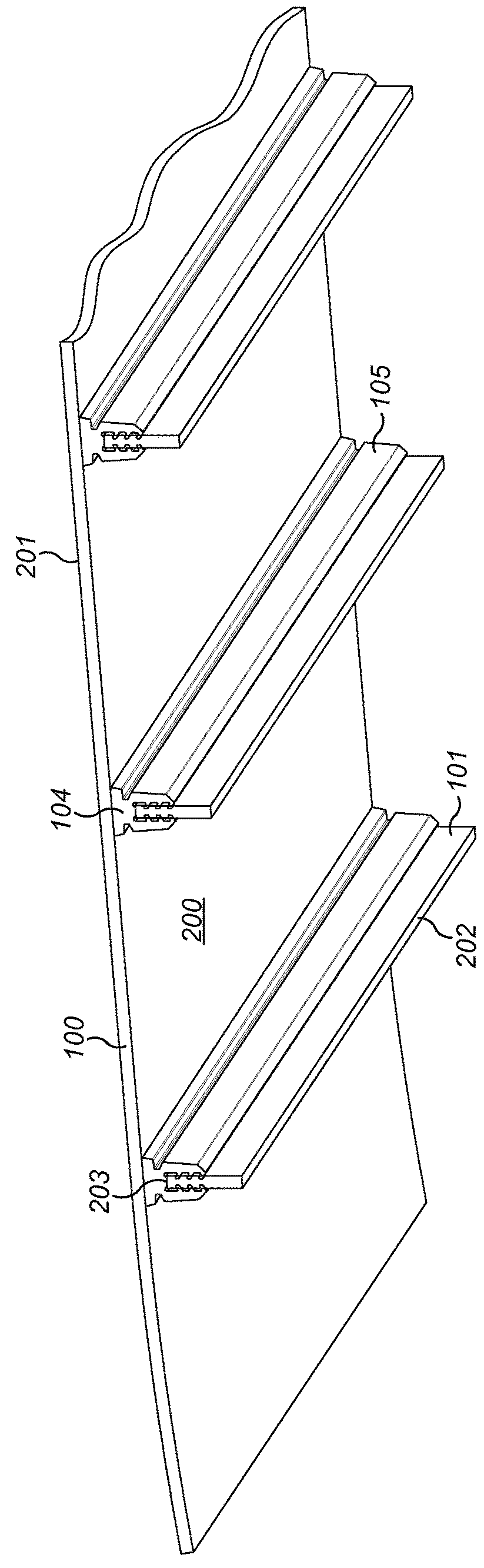
[0024]Referring to FIGS. 1 and 2, a vibrating screen deck comprises sheet-like cross-tensioned screening media 100 onto which may be deposited bulk material to be screened such as stones, gravel and the like. Media 100 typically comprises rubber or polyurethane and comprises an open structure (aperture) through which the bulk material may fall when deposited on an uppermost surface 201. Media 100 at its endmost edges 106 comprises hooks (not shown) for attachment to a fastening (not shown) provided on the sidewalls (not shown) of the screen deck so as to mount the media 100 under tension. A plurality of support beams 101 extend parallel to one another and to the sidewalls of the screen deck so as to be aligned generally perpendicular to the length of media 100 between end edges 106. Beams 101 typically comprise steel and have a generally rectangular cross-sectional profile having a lower elongate end surface 202 and an upper elongate end surface 203 positioned closest to and directl...


PUM


Abstract

An elongate capping is arranged to support cross-tensioned or pre-tensioned screening media at a screen deck. The capping includes a pair of arms to grip a carrier beam of the screen deck and a head attached to the arms via a neck. The head includes flexible widthwise extending flanges that are configured to bend and compress towards the arms to support the screening media when mounted on the head under tension.

Description

RELATED APPLICATION DATA[0001]This application is a § 371 National Stage Application of PCT International Application No. PCT / EP2015 / 050777 filed Jan. 16, 2015.FIELD OF INVENTION[0002]The present invention relates to a capping to support tensioned screening media at a screen deck.BACKGROUND ART[0003]Screening apparatus such as vibrating screen decks are used for a variety of applications and may comprise interchangeable square or rectangular screen elements that provide a screen surface upon which bulk material may be deposited and graded by size. Alternatively, the screen (commonly referred to as the screening media) may be of a cross-tensioned, length-tensioned or pre-tensioned media type having a sheet-like structure that extends between lengthwise extending sides of the screen deck. In particular, the tensioned screening media may be formed from wire mesh, metal sheet or reinforced polyurethane / rubber.[0004]Wire mesh media is advantageous as it is easy to mount, relatively low c...

Claims


Application Information

Patent Timeline
Patent Type & Authority Patents(United States)
IPC IPC(8): B07B1/49B07B1/46B07B1/36
CPCB07B1/4609B07B1/36B07B1/46B07B1/4645B07B1/48B07B1/16
Inventor MALMBERG, MATSFRANSSON, THOMAS
Owner SANDVIK INTELLECTUAL PROPERTY AB
Why Eureka
Try Eureka