
Gas exhaust system of film-forming apparatus, film-forming apparatus, and method for processing exhaust gas

a technology of film-forming apparatus and gas exhaust system, which is applied in the direction of positive displacement liquid engine, lighting and heating apparatus, separation process, etc., can solve the problems of reducing the efficiency of vacuum pump, clogging of pipes, and affecting so as to suppress the production of by-products and increase the efficiency of trapping

Active Publication Date: 2012-04-03
TOKYO ELECTRON LTD
View PDF20 Cites 7 Cited by
  • Summary
  • Abstract
  • Description
  • Claims
  • Application Information

AI Technical Summary

Benefits of technology

This approach ensures sufficient reaction to produce a stable, high-density by-product that can be efficiently trapped, reducing irregular clogging and the need for larger trap mechanisms, thereby increasing productivity and extending maintenance cycles.

Problems solved by technology

At this time, however, only 10% of the processing gas contributes to the reaction, and most of the processing gas remains unreacted.
When the by-products are cooled, a pipe is clogged or a vacuum pump is damaged.
Although it is preferable that the by-product is trapped by the trap mechanism in the form of a compound that is easily trapped and has a comparatively stable structure, the by-product produced at a flow rate ratio of each processing gas for film formation is not necessarily turned into a desired compound.
In practice, however, the reaction may proceed insufficiently, so that an unstable by-product or a by-product having an indefinite structure such as a complex or the like may be produced.
Accordingly, the trap mechanism needs to be scaled up due to hard to trap the by-product and, also, the trap mechanism may be irregularly clogged due to an unreliable generation state (density or the like) of a reaction product.

Method used


Image

  • Gas exhaust system of film-forming apparatus, film-forming apparatus, and method for processing exhaust gas
  • Gas exhaust system of film-forming apparatus, film-forming apparatus, and method for processing exhaust gas
  • Gas exhaust system of film-forming apparatus, film-forming apparatus, and method for processing exhaust gas

Examples


Embodiment Construction

[0030]Embodiments of the present invention will be described with reference to the accompanying drawings which form a part hereof. In the present embodiment, there will be described, as an example, a case where a TiN film is formed by CVD on a surface of a semiconductor wafer (hereinafter, referred to as “wafer”) as a substrate to be processed.

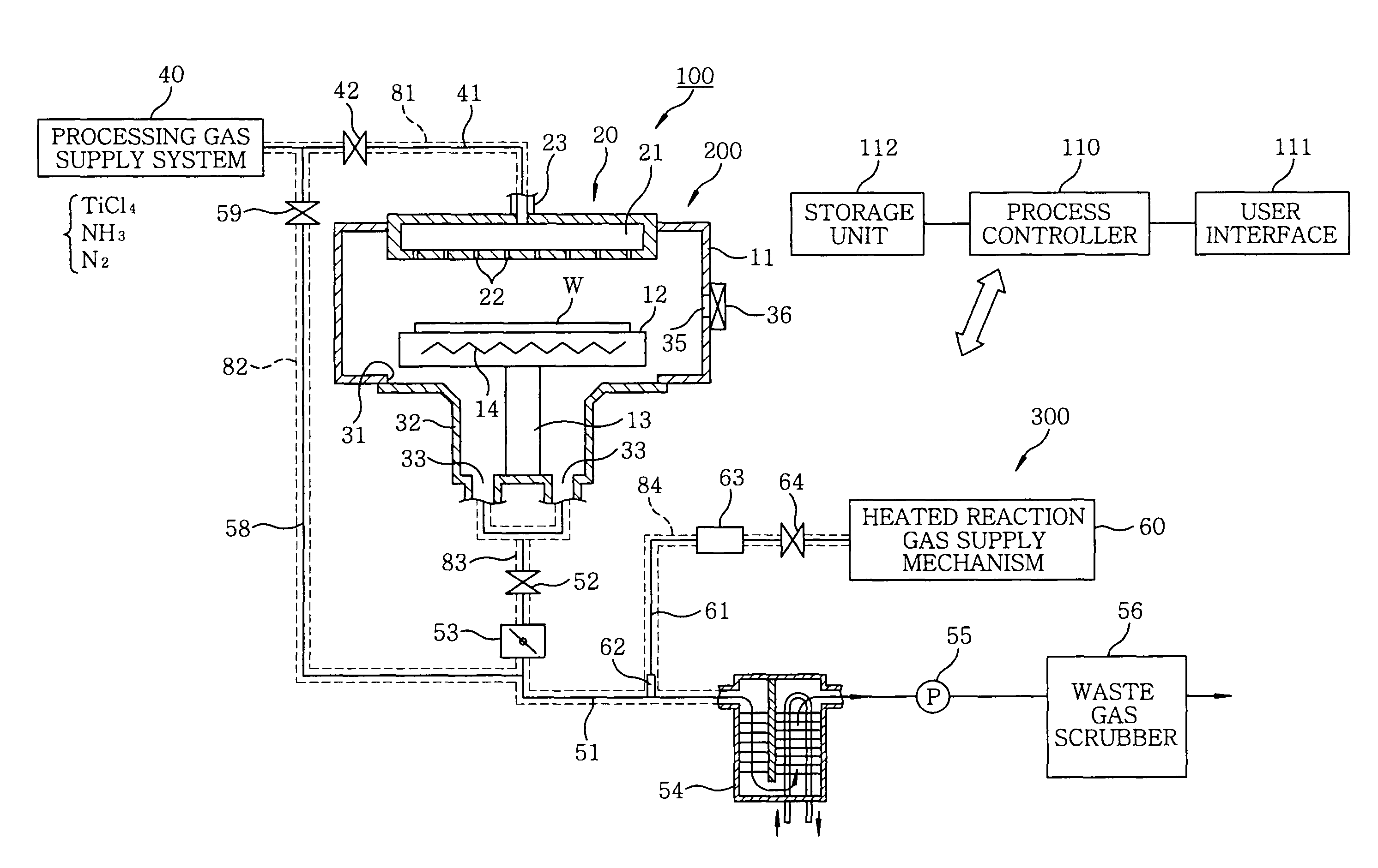
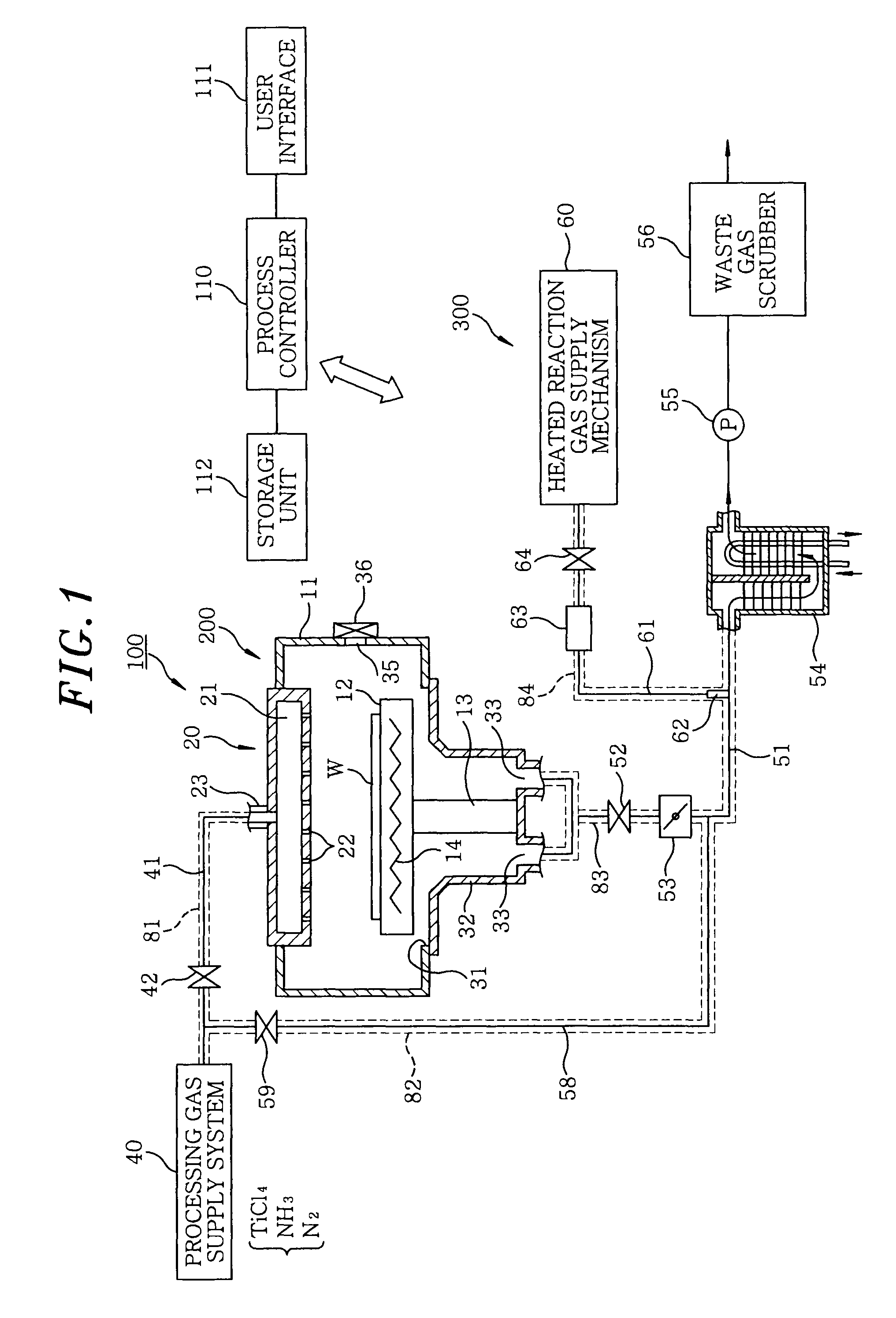
[0031]FIG. 1 is a schematic view of a film-forming apparatus having a gas exhaust system in accordance with an embodiment of the present invention.

[0032]A film-forming apparatus 100 includes a film-forming processing unit 200 and a gas exhaust system 300.

[0033]The film-forming processing unit 200 has a substantially cylindrical chamber (processing chamber) 11 made of aluminum or aluminum alloy (e.g., JIS A5052). In the chamber 11, a susceptor 12 for horizontally supporting a wafer W as a substrate to be processed is supported by a cylindrical supporting member 13 provided at a central bottom portion thereof. A heater 14 is buried in the suscep...


PUM

PropertyMeasurementUnit
inner diameteraaaaaaaaaa
temperatureaaaaaaaaaa

Abstract

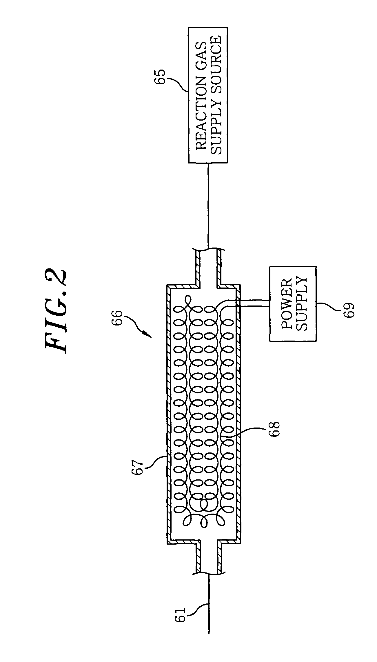
A film-forming apparatus includes a processing chamber, and TiCl4 gas and NH3 gas are supplied into the processing chamber for forming a TiN film on a substrate W in the processing chamber by CVD. The processing chamber has a gas exhaust system. The gas exhaust system includes a gas exhaust pipe for exhausting the exhaust gas in the processing chamber a trap mechanism provided to the gas exhaust pipe for trapping a by-product in the exhaust gas, and a heated reaction gas supply mechanism for supplying a heated reaction gas into the exhaust gas. The heated reaction gas is adapted to react with a component in the exhaust gas to produce a by-product. Specifically, NH3 gas is supplied by the heated reaction gas supply mechanism as the heated reaction gas, and NH4Cl is produced as the by-product.

Description

CROSS-REFERENCE(S) TO RELATED APPLICATIONS[0001]This application is a continuation application of pending U.S. application Ser. No. 12 / 295,675, filed on Oct. 1, 2008, the entire contents of which is incorporated herein by reference, which is a national phase of PCT / JP2007 / 057398, filed on Apr. 2, 2007. This application also claims priority to Japanese Application No. 2006-102920 filed on Apr. 4, 2006 and Japanese Application No. 2007-066650, filed on Mar. 15, 2007.FIELD OF THE INVENTION[0002]The present invention relates to a gas exhaust system of a film-forming apparatus for forming a predetermined film by CVD, a film-forming apparatus having the gas exhaust system, and a method for processing an exhaust gas.BACKGROUND OF THE INVENTION[0003]In manufacturing semiconductor devices, various processes, such as film formation, quality modification, oxidation / diffusion, etching and the like, are performed on a semiconductor wafer as a substrate to be processed.[0004]For the film formatio...

Claims


Application Information

Patent Timeline
Patent Type & Authority Patents(United States)
IPC IPC(8): C23C16/00B01D53/68
CPCC23C16/34C23C16/4412C23C16/52C23C16/4557
Inventor TSUDA, EINOSUKE
Owner TOKYO ELECTRON LTD
Learn More