Method for producing contoured holes

a contoured hole and drilling method technology, applied in the direction of machines/engines, light and heating equipment, turbines, etc., can solve the problems of significant heat intake, drilling through thermal barrier coatings, and a required dimensional accuracy as well as airflow capability, etc., to achieve a fast and inexpensive method of producing

Inactive Publication Date: 2018-05-15
ANSALDO ENERGIA IP UK LTD
View PDF8 Cites 4 Cited by
  • Summary
  • Abstract
  • Description
  • Claims
  • Application Information

AI Technical Summary

Benefits of technology

[0006]It is an object of the present disclosure to provide a method for manufacturing contoured holes. In an aspect of the disclosure a method shall be provided avoiding the drawbacks of the art. In a further aspect, a method shall be provided which allows a fast and inexpensive method of producing contoured holes. In still a further object of the disclosure, a method is provided for manufacturing cooling holes, in particular cooling holes for gas turbine components, and in particular film cooling holes. In a more specific aspect, such holes shall be manufactured, for instance, in blades, vanes, or platforms. A possible intended use of the holes as film cooling holes requires specific boundary conditions to be met, such as for instance inclining the holes into an intended hot gas flow direction, or shaping them as diffusors, such that the cooling air emanating on the hot gas side will flow as tangentially as possible over the surface to be cooled, and the cooling air flow does not interfere with the hot gas flow.
[0041]It may further be preferred if the cooling hole cross section widens from the wall second surface to the wall first surface thus forming a diffuser for a coolant flow from the wall second surface to the wall first surface. This will serve to reduce the velocity of the coolant emanating from the cooling hole and reduce interferences with the hot gas flow. The through hole then forms the smallest cross section and serves as a metering hole, determining the coolant mass or volume flow for a given pressure ratio between the wall first and second surface.

Problems solved by technology

While the first production method is time consuming and expensive, laser drilling may result in significant heat intake which may have an impact on the metallurgical quality, and also in backstrikes on an opposite wall of e.g. a hollow blade or vane.
Likewise, drilling through thermal barrier coatings and a required dimensional accuracy as well as airflow capability may be an issue in manufacturing cooling holes.

Method used


Image

  • Method for producing contoured holes
  • Method for producing contoured holes
  • Method for producing contoured holes

Examples


first embodiment

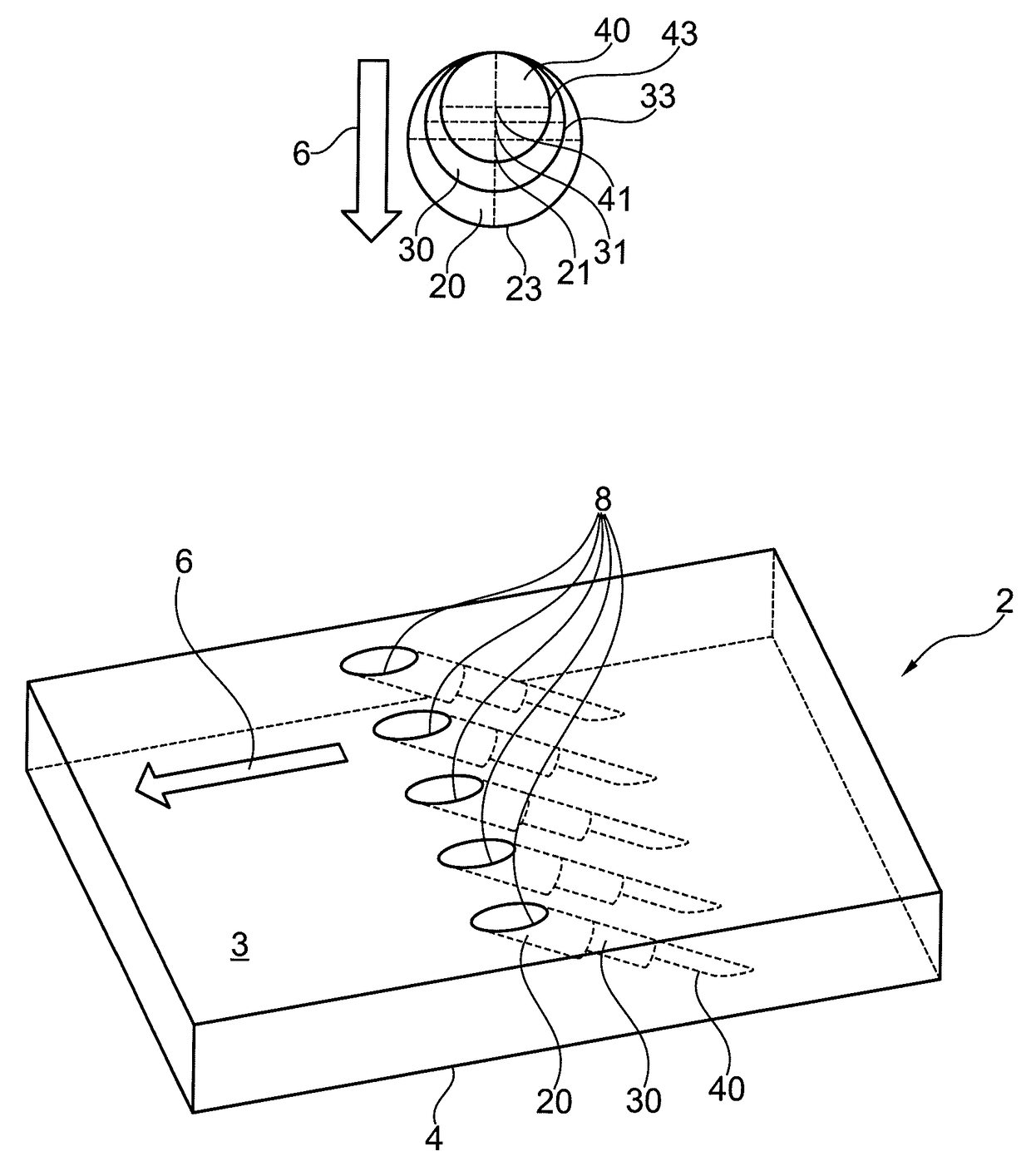
[0059]cooling holes is shown in FIG. 3. In the lower part of FIG. 3, a wall 2 is shown with a number of cooling holes 8 having a step-cylindrical geometry extending between a wall first surface 3 and second surface 4. The cooling holes are tilted in the intended hot gas flow direction 6. The cooling holes comprise a first non-penetrating hole 20 and a through hole 40. Through hole 40 has a smaller diameter than first non-penetrating hole 20. Through hole 40 is thus a metering hole which determines the cooling air mass or volume flow in defining the smallest cross section of a cooling hole 8. In the upper part of FIG. 3, axial views of a cooling hole are shown. The axis 41 of through hole 40 is parallel and offset with respect to the axis 21 of first non-penetrating hole 20. The offset is chosen such that the perimeters 23, 43 of the holes are tangent. Two configurations are shown, in which the through hole axis is offset upstream or downstream the intended hot gas flow direction.

[00...


PUM

PropertyMeasurementUnit
tilt angleaaaaaaaaaa

Abstract

A method for manufacturing a contoured hole, the hole being manufactured in a wall, the wall comprising a first, a second surface, and a wall thickness between the wall first and second surface. The comprises manufacturing a first non-penetrating hole extending from the first surface and into the wall, wherein a distal end of the first hole is located within the wall such that the first hole does not penetrate the wall second surface, and manufacturing a through hole, wherein the through hole is fluidly connected with first hole and penetrates the wall second surface.

Description

TECHNICAL FIELD OF INVENTION[0001]The present disclosure relates to the field of producing contoured holes as disclosed.[0002]Such holes may be applied as film cooling holes e.g. in gas turbines, such as for instance on expansion turbine blades or vanes.BACKGROUND OF INVENTION[0003]In cooling thermally highly loaded components of gas turbine engines often film cooling is applied. For film cooling, cooling fluid is guided onto a thermally loaded surface of a gas turbine component, such as for instance a blade, a vane, or a platform, and is intended to flow along this surface. Consequently, film cooling holes need to be inclined and diffuser shaped in order to provide a coolant layer directed along the component surface and to avoid separation of the coolant flow from the component surface.[0004]It is known to produce such cooling holes e.g. by means of electrochemical methods or laser drilling. While the first production method is time consuming and expensive, laser drilling may resu...

Claims


Application Information

Patent Timeline
Patent Type & Authority Patents(United States)
IPC IPC(8): B23P15/02F23R3/00F01D9/04F01D25/14F01D25/12F01D5/18B23P15/04B23B35/00
CPCB23B35/00B23P15/04F01D5/186F01D9/041F01D25/12F01D25/14F23R3/002B23P15/02Y10T29/49341B23B2215/76B23B2220/32F05D2220/32F05D2230/10F05D2240/12F05D2240/30F05D2240/81F05D2260/202F05D2250/70
Inventor LUKETIC, IVANPARALIKAS, IOANNISWARDLE, BRIAN KENNETH
Owner ANSALDO ENERGIA IP UK LTD
Why Eureka
Try Eureka