Biased blind side temporary fasteners, systems and methods

a temporary fastener and blind side technology, applied in the field of biased blind side temporary fasteners, systems and methods, can solve the problems of not being subject to very little restraint, fasteners are more likely to react negatively to the rotation of work pieces, and fail to address lateral play issues, so as to prevent unintended egress of the plunger finger distal end, prevent the egress of the plunger finger, and engage the collet body better

Active Publication Date: 2018-05-15
CENTRIX
View PDF34 Cites 3 Cited by
  • Summary
  • Abstract
  • Description
  • Claims
  • Application Information

AI Technical Summary

Benefits of technology

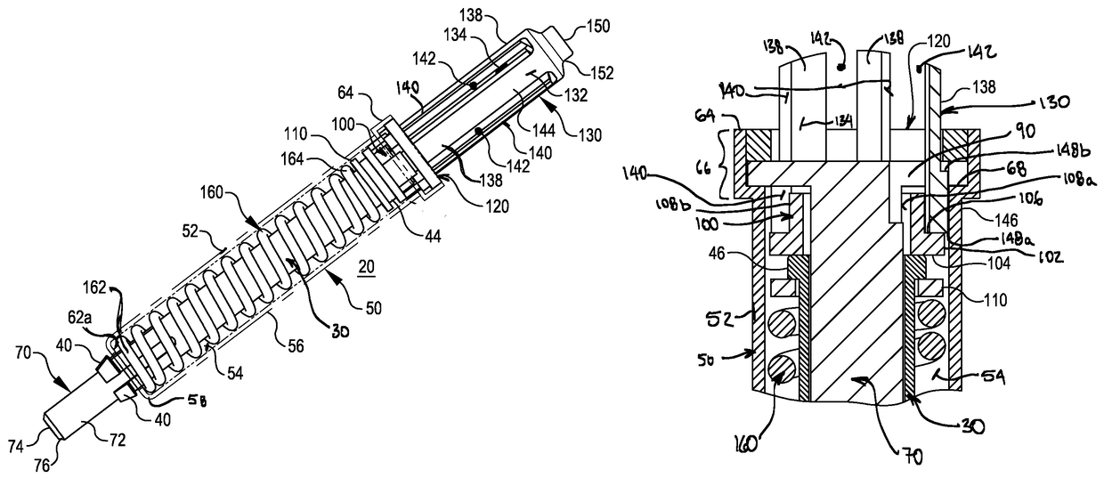
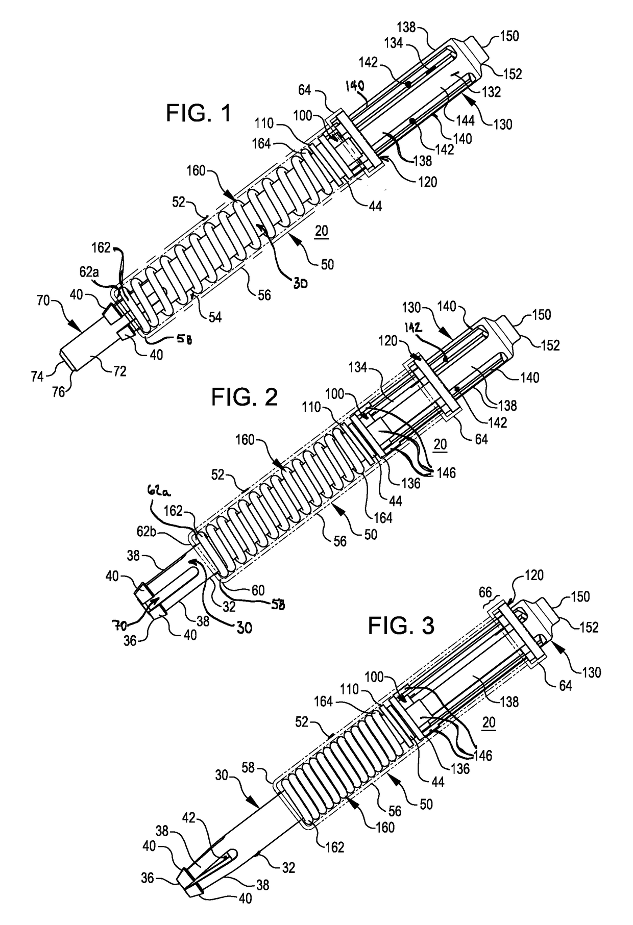
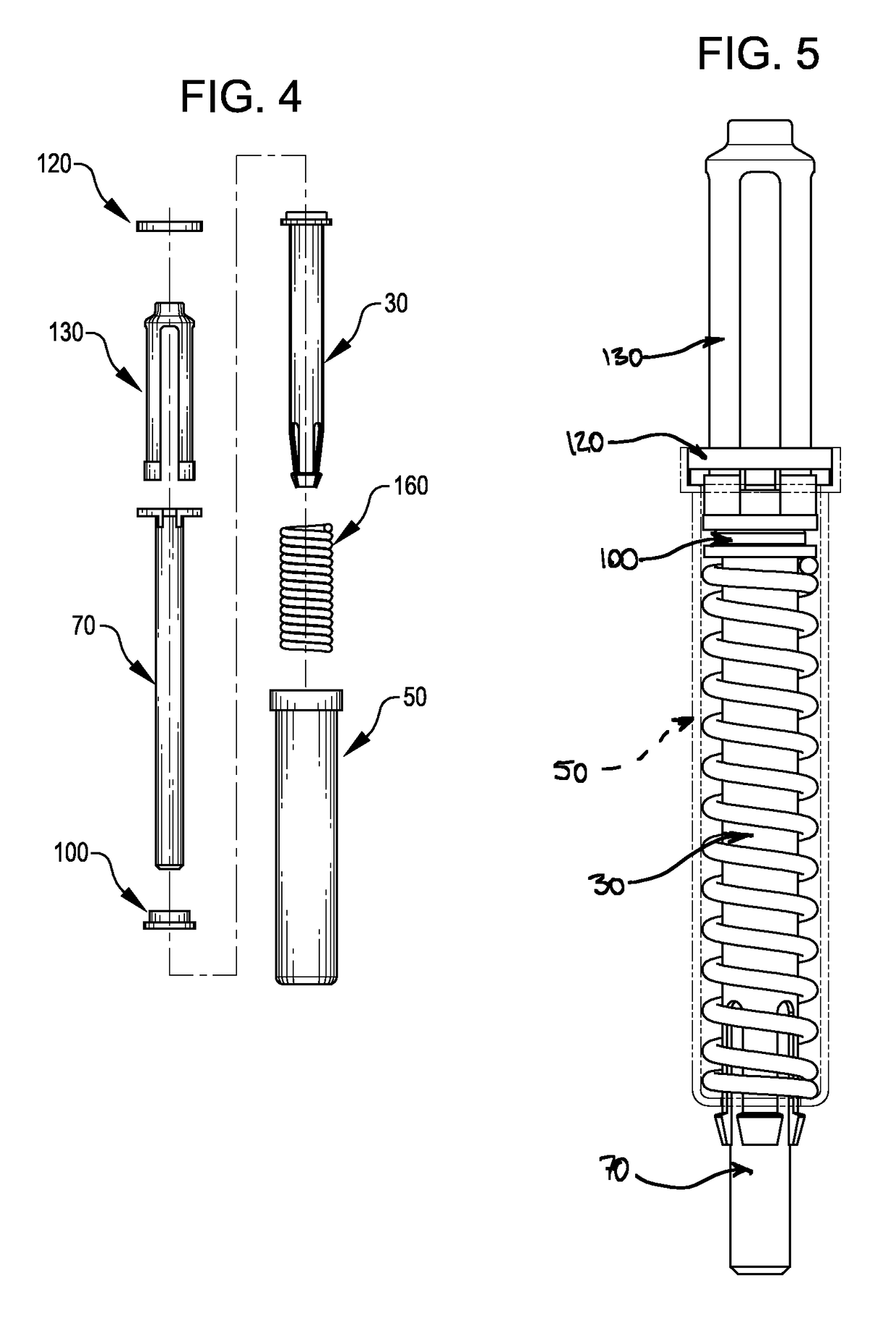
[0005]A first series of fastener embodiments according to the invention comprises an elongate, hollow case for substantially housing a generally cylindrical collet body and a bias means, and at least partially housing a central rod having a proximal end linked to a proximal portion of the case by a web element, and further comprises a plunger for temporarily overcoming an inherent clamping bias, thus allowing for the insertion of a fastener into the work pieces' holes, wherein the plunger is formed to substantially translatably pass through the web element. Through use of a generally cylindrical collet body, a high level of work piece alignment keyed from the holes or orifices can be achieved, in many instances resulting in a total clearance between the collet body of the fastener and the work piece hole or orifice of less than 0.001″ in any radial direction.
[0010]It should be noted that when the collet body fingers are in a radially converged state, the maximum external surface diameter at its gripping portions is less than any diameter of a working portion of the collet body (as used herein, the working portion of the collet body is that portion of the collet body that may reside or outside the case during operation of a fastener embodiment, i.e., the stoke of the collet body). By establishing this limit to the external surface diameter, the distal end of the collet body will be able to traverse each work piece hole in order for the gripping portions to reach an opposing work piece reactive surface. As will be described in more detail below, this limitation also facilitates fabrication of certain invention embodiments.
[0014]The bias means, which is often times a compression spring, is held substantially within the confines of the case and engages the case and the collet body. In many embodiments, the bias means reacts against the reduced diameter portion of the case at a first end and an increased diameter portion at the proximal end of the collet body. As a consequence of this arrangement, movement of the collet body distal end towards the case reduced diameter portion is resisted by the bias meas. This resistance is elastic in nature and creates a restorative force between the collet body distal end and the case reduced diameter portion when the collet body is displaced from its nominal position.
[0016]The plunger is the element responsible for imparting translation to the collet body when its compression force exceeds the bias of the bias means. Thus, when the restorative force of the bias means is overcome by the compression force imparted by the plunger, the distal end of the collet body is caused to translate towards distal end of the rod. Depending upon the length of the rod exposed to the environment, the distal end of the collet body will at some point translate past the distal end of the rod, thereby permitting a radial constriction bias in the collet body fingers to radially converge the fingers. In this state, the maximum diameter of the collet body at the gripping elements is equal to or less than the outer diameter of the collet body at its working portion. Those persons skilled in the art will of course appreciate that even if the fingers are not fully collapsed, an insertion force presented against the gripping elements leading face, which are acute to the collet body axis, will impart an additional radial convergence force, thereby causing further radial convergence and functionally achieving the desired diameter reducing effect.
[0018]The web element may be part of either the case or the rod, or may be a discrete component introduced during assembly of a fastener according to these features of the invention. Preferably, the web element comprises a plurality of radially aligned arms like spokes on a wheel where the hub is the rod and the wheel is the case inner surface. By having a discontinuous periphery, i.e., the case inner surface is exposed within the arc sections, the plunger outer surface diameter can closely match that of the case inner surface diameter, and benefit from a close fit relationship there with as described below, and can further better engage the collet body. In any event, the web element is at least temporarily fixedly attached to both the case and the rod.
[0019]To prevent unintended egress of the plunger fingers, many invention embodiments have fingers that comprise a radially extending flange that interferes with a locking ring or washer inserted at the web element after insertion of the plunger fingers. This locking ring or washer may then serve two purposes: to prevent egress of the plunger finger distal ends from inside the case via the web element openings, and prevent egress of the web element (and therefore also the rod) from inside the case.

Problems solved by technology

While this style of fastener may be adequate in certain situations, e.g., low tolerance material processing, the legs are at best only partially hemispherical, which fails to address issues of lateral play between the work pieces when compressively held together by the fastener.
Moreover, such fasteners are more likely to react negatively to work piece rotation given the inclusion of three or more elements that are not mechanically linked to each other (there is intentional “float” between all components to permit translation of the legs relative to the projection, but this float is subject to very little restraint in the plane of the projection).

Method used


Image

  • Biased blind side temporary fasteners, systems and methods
  • Biased blind side temporary fasteners, systems and methods
  • Biased blind side temporary fasteners, systems and methods

Examples


Embodiment Construction

[0039]Preface: The terminal end of any numeric lead line in the several drawings, when associated with any structure or process, reference or landmark described in this section, is intended to representatively identify and associate such structure or process, reference or landmark with respect to the written description of such object or process. It is not intended, nor should be inferred, to delimit or define per se boundaries of the referenced object or process, unless specifically stated as such or facially clear from the drawings and the context in which the term(s) is / are used. Unless specifically stated as such or facially clear from the several drawings and the context in which the term(s) is / are used, all words and visual aids should be given their common commercial and / or scientific meaning consistent with the context of the disclosure herein.

[0040]With the foregoing in mind, the following description is presented to enable a person skilled in the art to make and use the cl...


PUM


Abstract

Biased blind side fasteners and related methods for temporarily securing together at least two work pieces that each define a hole through which at least a portion of the fastener may pass. Fastener embodiments include an elongate, hollow case for substantially housing a generally cylindrical collet body and a bias element for urging the collet body into the case, and at least partially housing a central rod having a proximal end linked to a proximal portion of the case by a web element and a distal end extending from the case. Such embodiments further include a translatable plunger for temporarily overcoming the urging of the bias element and causing extension of the collet body away from the case, thereby permitting insertion of a fastener into the work pieces' holes, wherein the plunger is formed to substantially translatably pass through the web element.

Description

BACKGROUND OF THE INVENTION[0001]Biased blind side temporary fasteners are used primarily to hold at least one work piece, commonly a panel-type material, in registry with another work piece, each defining at least one commonly aligned hole through which the fastener may at least partially pass. Once the two or more work pieces are so aligned and retained, they may be subject to subsequent material processing, e.g., welding, permanent fastening, etc. Examples of environments wherein such fasteners are commonly used include the aerospace and automotive industries.[0002]A common form of such fasteners is the “CLECO” fastener, an example of which can be found in U.S. Pat. No. 4,537,542. In such fasteners, a static central projection anchored to opposing wall portions of the fastener case separates a pair of legs that axially translate about the projection in the working region of the fastener. Depressing a plunger causes the legs to translate along the projection until the distal ends ...

Claims


Application Information

Patent Timeline
Patent Type & Authority Patents(United States)
IPC IPC(8): F16B19/10
CPCF16B19/109Y10T403/602F16B5/06F16B2005/0678
Inventor MCCLURE, TRAVIS D.
Owner CENTRIX
Why Eureka
Try Eureka