Light stick

a technology of light sticks and lanterns, which is applied in the direction of lighting and heating apparatus, lighting support devices, light source combinations, etc., can solve the problems of non-satisfactory prior lanterns of this type, limited the need for lanterns to be generally upright, and non-directional exposed bulbs

Active Publication Date: 2018-05-15
DONNAN JOSEPH
View PDF1 Cites 3 Cited by
  • Summary
  • Abstract
  • Description
  • Claims
  • Application Information

AI Technical Summary

Benefits of technology

[0011]A light stick, primarily useful in the locomotive industry for signally between train personnel, includes a longitudinally extending housing which contains a first light source and a second light source. The first light source, which is disposed on a top side of the housing and which extends therefrom to a midline of a proximal lateral wall and to a midline of an oppositely situated distal lateral wall of the housing, provides for general purpose illumination of the light stick. The second light source, which is positioned towards a forward end of the housing, provides illumination for purposes of signaling. The light stick includes a lens cap, which is positioned at a forward end of the housing, and from which the illumination from the second light source may extend. Preferably, the light that is emitted from the lens cap has a blue color.
[0012]These and other features and advantages of the present invention will be more fully understood from a reading of the following detailed description with reference to the accompanying drawings.

Problems solved by technology

Modern lanterns have their origins in the oil lanterns of the nineteenth century, and so many of the signals now in use (e.g., swinging the lantern through an arc with the arm lowered) were developed on this basis, with the limitation that the lantern needed to be held generally upright.
Although they meet the foregoing requirements (i.e., illumination and signaling) in a general sense, prior lanterns of this type have not been wholly satisfactory.
The single exposed bulb is non-directional, and when viewed from the side is inadequately bright to be seen by the engineer at long distances (e.g., at the end of a long train); moreover, at certain angles light from the bulb is blocked by the protective struts.
However, using additional bulbs for greater brightness and visibility is not a viable solution due to increased drain on the battery.
The lanterns are often kept lit throughout nighttime hours, so that using additional bulbs would mean that in many instances the battery would be dead before the end of the shift, Even with existing two-bulb lanterns, each operating region of a major railroad consumes several thousand batteries every night, at considerable cost.
Other deficiencies of traditional trainman's lanterns include a weak and poorly distributed main “spot” beam and inadequate durability.
For example, the struts that support the guard ring around the bottom of the lantern described above must be relatively narrow in order to avoid even worse blockage of the bulb, so that the protective cage is relatively fragile and is smashed with alarming regularity.
Another problem with the prior art is that traditional trainsman's lanterns are heavy and cumbersome.
These lanterns are designed with large bail handles which allow an operator to slide the lantern down the operator's arm as the operator climbs onto a car or locomotive, which is physically uncomfortable, thereby causing the operator to hold the lantern in the operator's hand, thereby leaving only one hand available to support the operator as he climbs onto the car or locomotive, which poses an obvious safety risk to the operator.

Method used


Image

  • Light stick
  • Light stick
  • Light stick

Examples


Embodiment Construction

[0020]Preferred embodiments of the present disclosure will he described hereinbelow with reference to the accompanying drawings. In the following description, well-known functions or constructions are not described in detail to avoid obscuring the invention in unnecessary detail. Throughout the drawings, like reference numerals represent like elements.

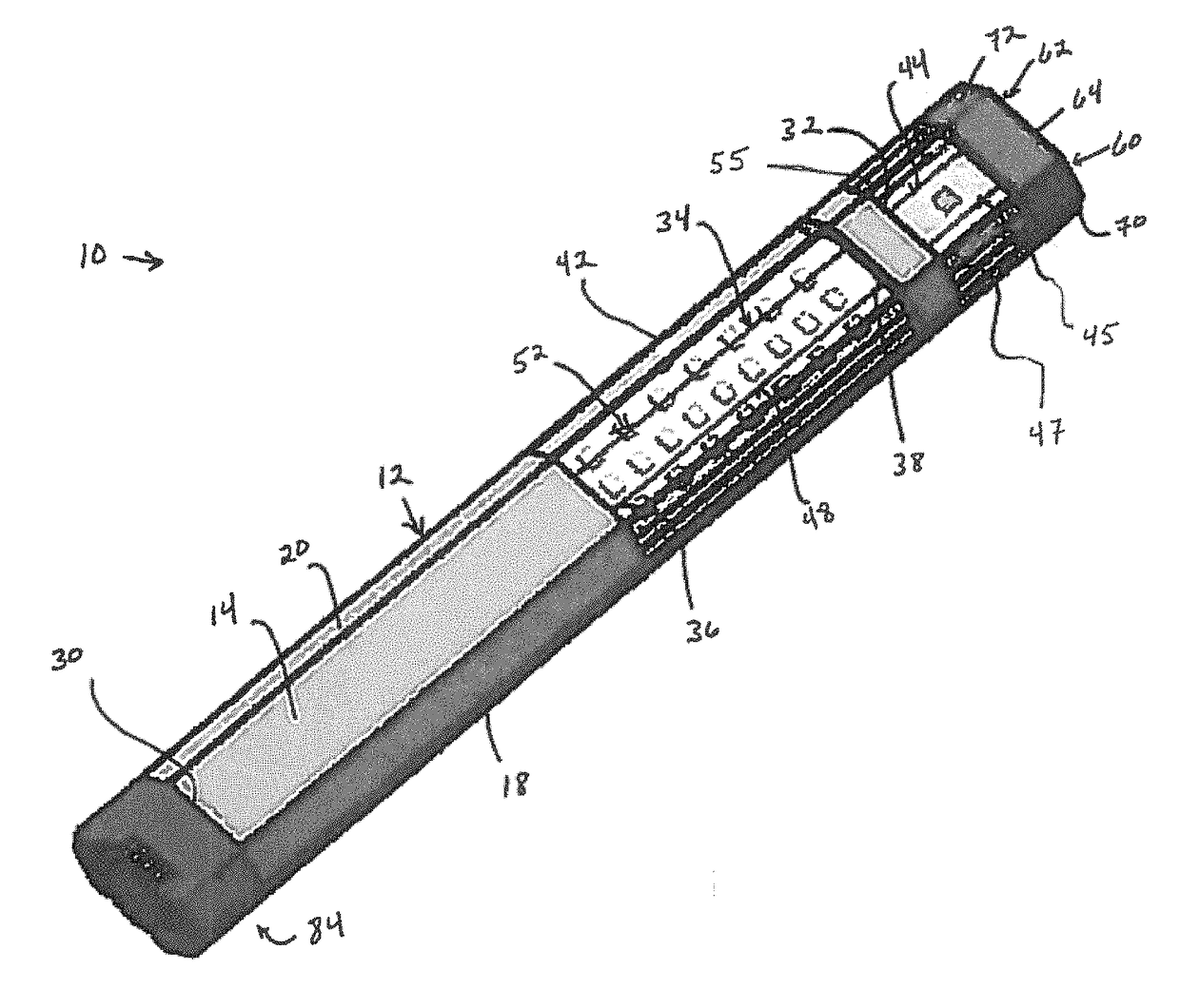
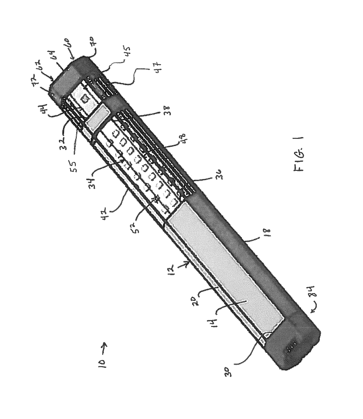
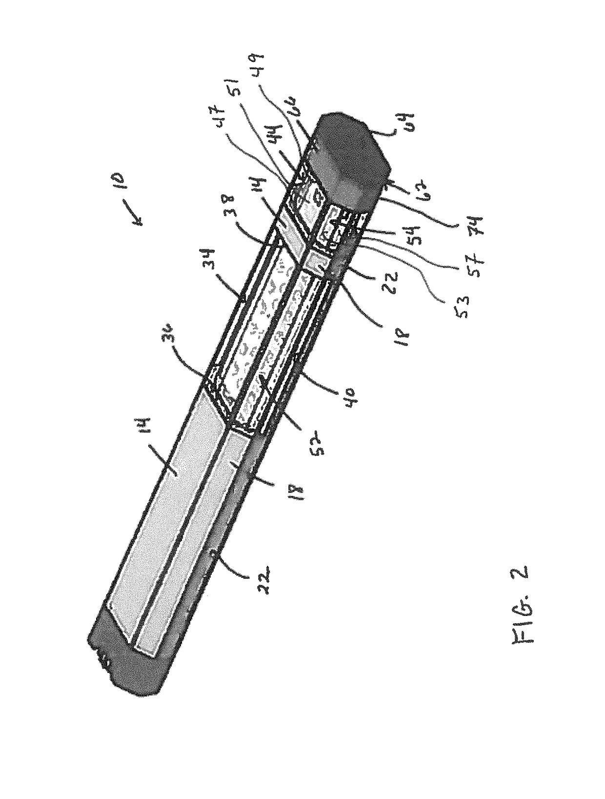
[0021]Referring to FIGS. 1-8, a light stick 10 according to an embodiment of the present disclosure is shown. Referring to FIGS. 1-6, light stick Its comprises a housing 12 having an octagonal shaped body which extends along a longitudinal Y axis. To that end, housing 12 has a top side 14 oppositely situated to a bottom side 16, an upper proximal lateral side 18 oppositely situated to an upper distal lateral side 20, a medial proximal lateral side 22 oppositely situated to a medial distal lateral side 24, and a lower proximal lateral side 26 oppositely situated to a lower distal lateral side 28. Upper proximal and distal lateral sides ...


PUM


Abstract

A light stick, primarily useful in the locomotive industry for signally between train personnel, includes a longitudinally extending housing which contains a first light source and a second light source. The first light source provides for general purpose illumination of the light stick. The second light source provides illumination primarily for purposes of signaling. The light stick may include a lens cap which is positioned at a forward end of the housing, and from which the illumination from the second light source may extend. Preferably, the light that is emitted from the lens cap has a blue color for purposes of railroad signaling.

Description

BACKGROUND OF THE INVENTION[0001]1. Field of the Invention[0002]The present invention relates generally to signaling lanterns used in the railroad industry, and, more particularly, to a trainman's lantern having both axially and radially directed illumination.[0003]2. Background of the Invention[0004]Trainman's lanterns are specialized lighting apparatus used in the railroad industry for purposes of both signaling and illumination. In particular, trainman's lanterns are used to transmit signals from the brakeman or switchman to the engineer in the locomotive, when coupling / uncoupling cars, moving on to switches and sidings, and so on. Modern lanterns have their origins in the oil lanterns of the nineteenth century, and so many of the signals now in use (e.g., swinging the lantern through an arc with the arm lowered) were developed on this basis, with the limitation that the lantern needed to be held generally upright. Still other signals evolved with the later adoption of electric l...

Claims


Application Information

Patent Timeline
Patent Type & Authority Patents(United States)
IPC IPC(8): F21S4/00F21K9/237B61L5/18F21K9/66F21K9/235F21K9/238
CPCF21K9/237B61L5/18F21K9/66F21K9/235F21K9/238B61L5/1845B61L5/1854F21L4/00F21V3/02F21V5/04F21V15/01F21V21/0965F21V23/0414F21Y2115/10F21Y2113/13
Inventor DONNAN, JOSEPH
Owner DONNAN JOSEPH
Why Eureka
Try Eureka