

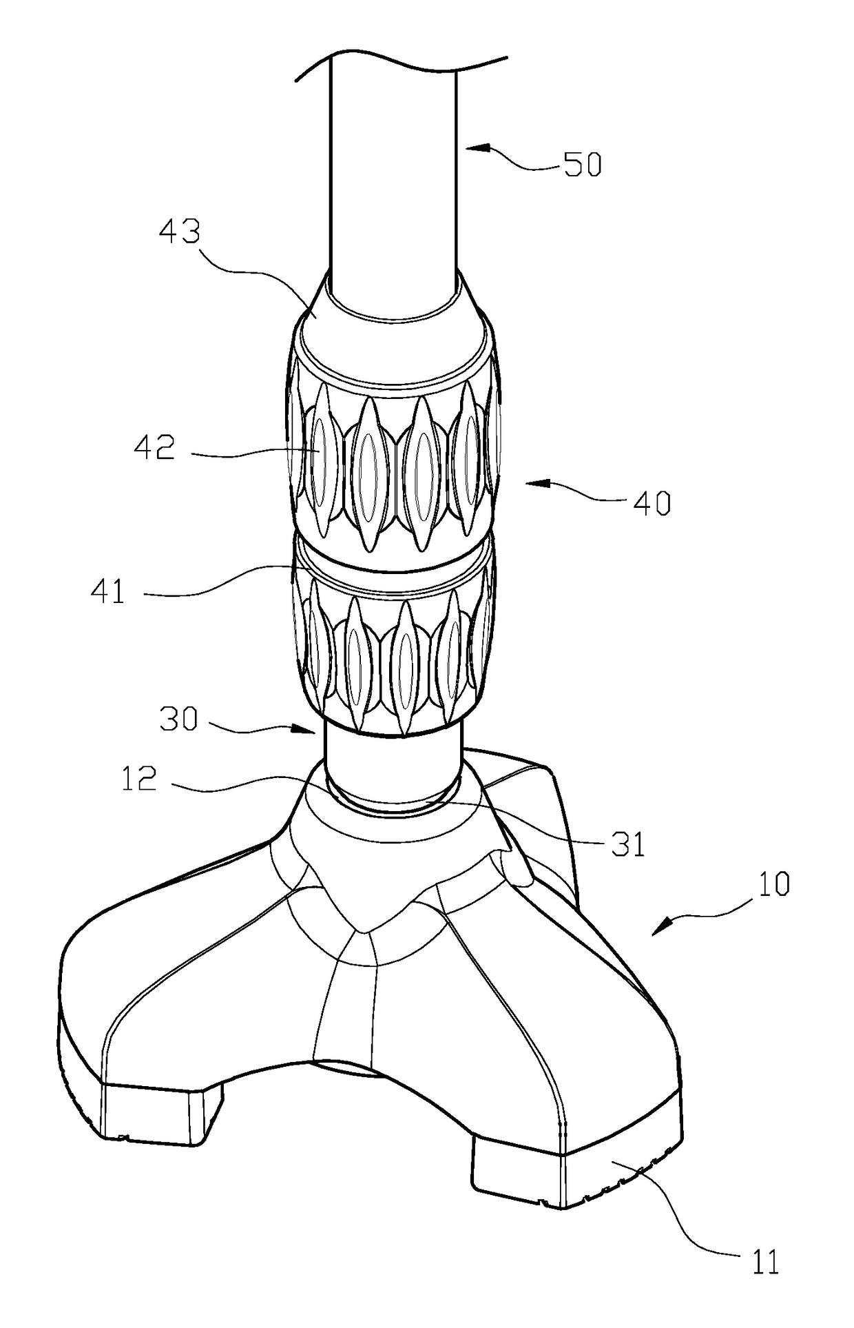
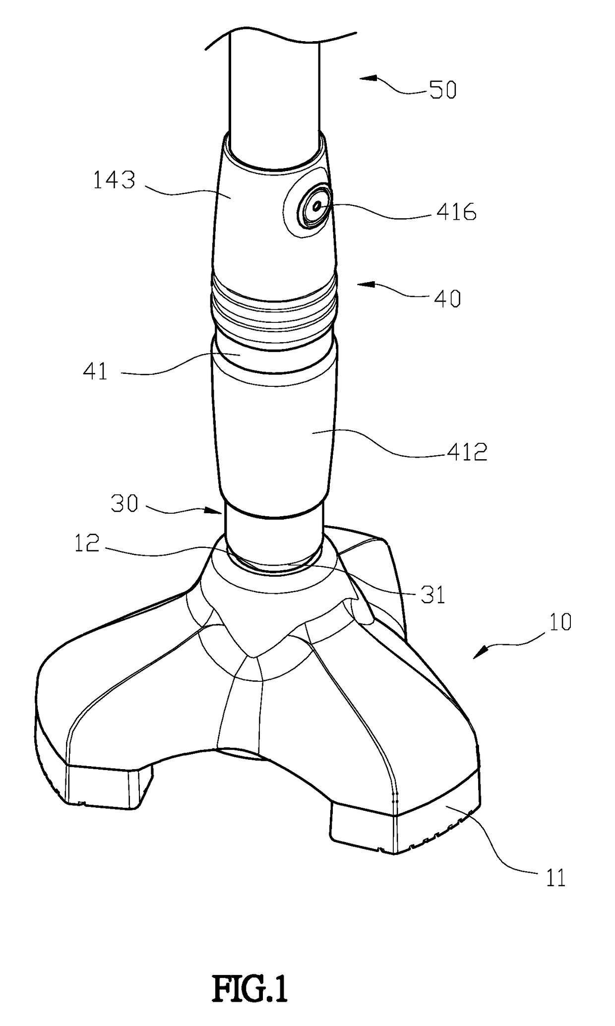
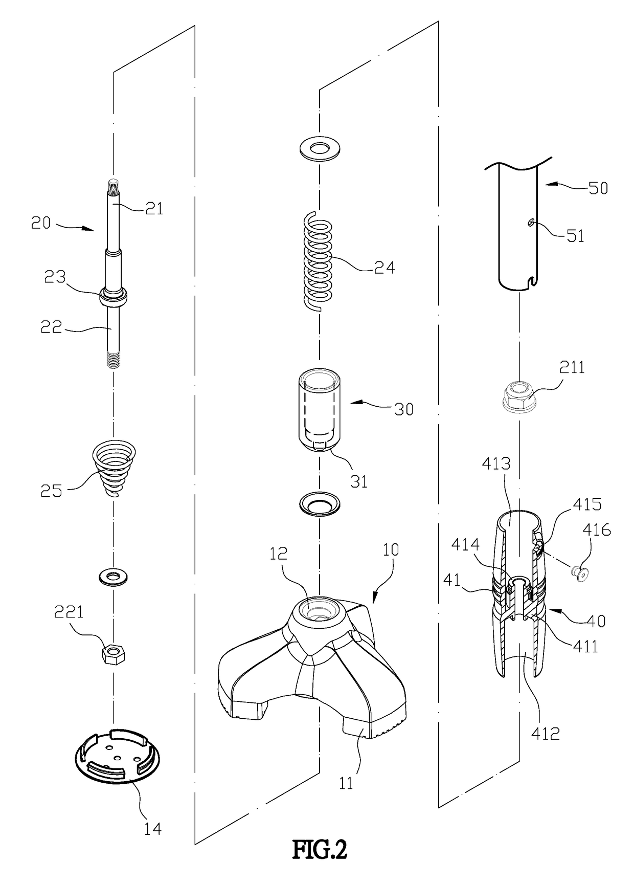
Base structure for walking stick
a technology of walking sticks and bases, which is applied in the field of base structures, can solve the problems of lowering reliability and safety, easy damage to rubber pads disposed on the conventional walking sticks, and lowering the maneuverability of walking sticks, so as to improve stability, buffer and absorb shock, and improve the effect of tightening
- Summary
- Abstract
- Description
- Claims
- Application Information
AI Technical Summary
Benefits of technology
Problems solved by technology
Method used
Image

Examples
Embodiment Construction
[0017]The detailed description set forth below is intended as a description of the presently exemplary device provided in accordance with aspects of the present invention and is not intended to represent the only forms in which the present invention may be prepared or utilized. It is to be understood, rather, that the same or equivalent functions and components may be accomplished by different embodiments that are also intended to be encompassed within the spirit and scope of the invention.
[0018]Unless defined otherwise, all technical and scientific terms used herein have the same meaning as commonly understood to one of ordinary skill in the art to which this invention belongs. Although any methods, devices and materials similar or equivalent to those described can be used in the practice or testing of the invention, the exemplary methods, devices and materials are now described.
[0019]All publications mentioned are incorporated by reference for the purpose of describing and disclos...
PUM
 Abstract
Description
Claims
Application Information