Blade combination method of crusher and combined blade of same

A combination method and pulverizer technology, applied in the direction of grain processing, etc., can solve the problems of difficult to achieve machining accuracy, complicated tool changing process, loose blades, etc., and achieve the effect of improving the reliability of cooperation, convenient installation and maintenance, and easy replacement

Inactive Publication Date: 2011-09-28
SHANGHAI DIANJI UNIV +1
View PDF6 Cites 5 Cited by
  • Summary
  • Abstract
  • Description
  • Claims
  • Application Information

AI Technical Summary

Problems solved by technology

The method of fixing with a non-threaded convex structure is to use a convex structure to clamp the blade in the cutter head to achieve fixation. However, when the blade needs to be replaced after this structure is worn out, the cutter head assembly must be disassembled to replace it. The blade, the process of changing the blade is more complicated and difficult to operate
Using the method of conical radial extrusion to fix the blade, in the process of positioning and tightening, with the increase of the conical head, it cooperates with the blade, and is squeezed by the relative conical radial direction, so it is difficult to accurately position and fix the blade in the axial direction. problems, and the machining accuracy is difficult to achieve, it is easy to cause loosening of the axial clearance of the blade, which affects the safe operation of the entire crushing machine
In order to solve the above problems, there is a method of side-mounted screws, that is, the axis of the screw is perpendicular to the axis of the blade. Although this can solve the problem of fixing, when the cutterhead rotates at high speed, the side-mounted screws are vulnerable to the impact of shear force. , it is very easy to deform or loosen the screws radially after vibration, and it is not very convenient for installation and maintenance.

Method used


Image

  • Blade combination method of crusher and combined blade of same
  • Blade combination method of crusher and combined blade of same
  • Blade combination method of crusher and combined blade of same

Examples


Embodiment Construction

[0024] The specific embodiments of the present invention are given below in conjunction with the accompanying drawings, but it should be pointed out that the implementation of the present invention is not limited to the following embodiments.

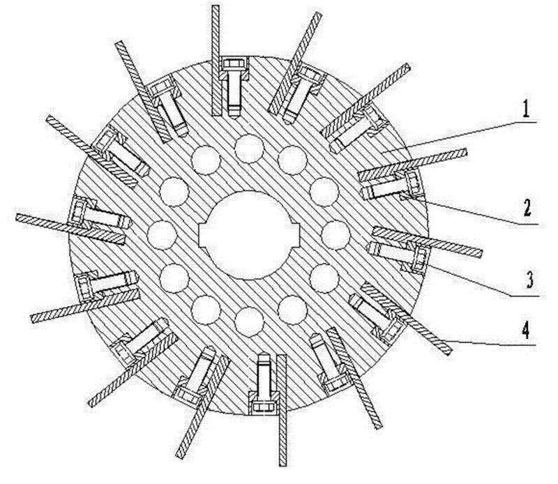
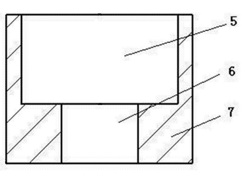
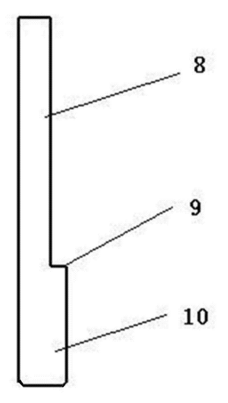
[0025] The main technical point of the blade combination method of a pulverizer in the present invention is: cut out parallel stepped grooves that are not synchronized with the angle of the cutter head to the center line on the edge of the cutter head cylinder toward the center of the circle (that is, the parallel stepped groove The centripetal line will not converge to the center point of the cutter head), insert the blade with a flat side and a concave-convex structure on the other side into the parallel stepped groove from the edge of the cutter head from the convex end, and the blades should be distributed in odd numbers. The distance between them should be equal, so that the installed blades are forward inclined, that is, the head o...


PUM


Abstract

The invention relates to the technical field of crushing machinery, in particular to a blade combination method of a crusher and a combined blade of the same. The combined blade is characterized in that a parallel-type stepped slot asynchronous with the angle of a centripetal line of a cutter is cut on the edge of a cutter cylinder, which is in the circle center direction, for holding blades; onesurface of each blade is of a concave-convex structure, the blades are embedded into the parallel-type stepped slot starting from convex surfaces of the blades, concave-convex shoulders of the bladesare parallel to the parallel-type stepped slot in a micro-interference manner, pressing blocks press the concave-convex shoulders of the blades in the parallel-type stepped slot in a radial clearancemanner and the pressing blocks are fastened on the edge of the cutter with backstop screws, and the tail parts of the tightened backstop screws are hidden in screw grooves of the pressing blocks; andan odd number of blades are distributed on the cutter at equal intervals. The invention has the positive effects that the blades are more easily fastened due to the arrangement mode, thereby effectively preventing the blades from being loosened in case of vibration, and the blades are conveniently installed, maintained and replaced, thus improving the operating efficiency of the crusher.

Description

technical field [0001] The invention relates to the technical field of pulverizing machinery and equipment, in particular to a method for combining blades of a pulverizer and combined blades thereof. Background technique [0002] The blade is the main part of the crushing material in the crushing machine, and it is installed on the cutter head. During the crushing process of the crushing machine, the blade rotates with the cutter head at high speed, and the wear of itself is particularly large while crushing the material, and the fixity of the connection and the reliability of the work will also be affected. Therefore, the blade needs to be replaced and maintained frequently. and maintenance. [0003] At present, the fixing methods of the pulverizer blade include a method of fixing with a non-thread tight convex structure, and a method of fixing with conical radial extrusion. The method of fixing with a non-threaded convex structure is to use a convex structure to clamp th...

Claims


Application Information

Patent Timeline
Patent Type & Authority Applications(China)
IPC IPC(8): B02C18/18
Inventor 陈萌林左家乐喻竑杰汤学华端木希敏
Owner SHANGHAI DIANJI UNIV
Why Eureka
Try Eureka