Vehicle power adjusting device

a technology for adjusting devices and vehicles, which is applied to vehicle heating/cooling devices, vehicle components, transportation and packaging, etc., can solve the problems of increasing air pollution, excessive power generation of conventional vehicles, and wasting more energy for vehicles, so as to save oil consumption, generate enough power, and save more energy for vehicles

Inactive Publication Date: 2018-05-22
ATALI TECH
View PDF1 Cites 0 Cited by
  • Summary
  • Abstract
  • Description
  • Claims
  • Application Information

AI Technical Summary

Benefits of technology

[0010]The purpose of the present invention is to provide a vehicle power adjusting device which can shut down the auxiliary dynamic load when the vehicle just starts moving or is in an insufficient power situation.
[0018]Compared with the prior art, the present invention has the beneficial effects are that the control chip detects the vehicle power condition, when vehicle is underpowered, the auxiliary dynamic load will be shut down for a few seconds to provide enough power for saving the oil consumption. Secondly, the vehicle power adjusting device can be used in the external or internal type which will not only generate enough power, but also save more energy for the vehicle.

Problems solved by technology

Therefore, the conventional vehicles are easy to produce power excessive or wasted condition.
But, the larger air capacity for the vehicle, the more carbon monoxide will be produced and the more serious air pollution will be caused.

Method used


Image

  • Vehicle power adjusting device
  • Vehicle power adjusting device
  • Vehicle power adjusting device

Examples


first embodiment

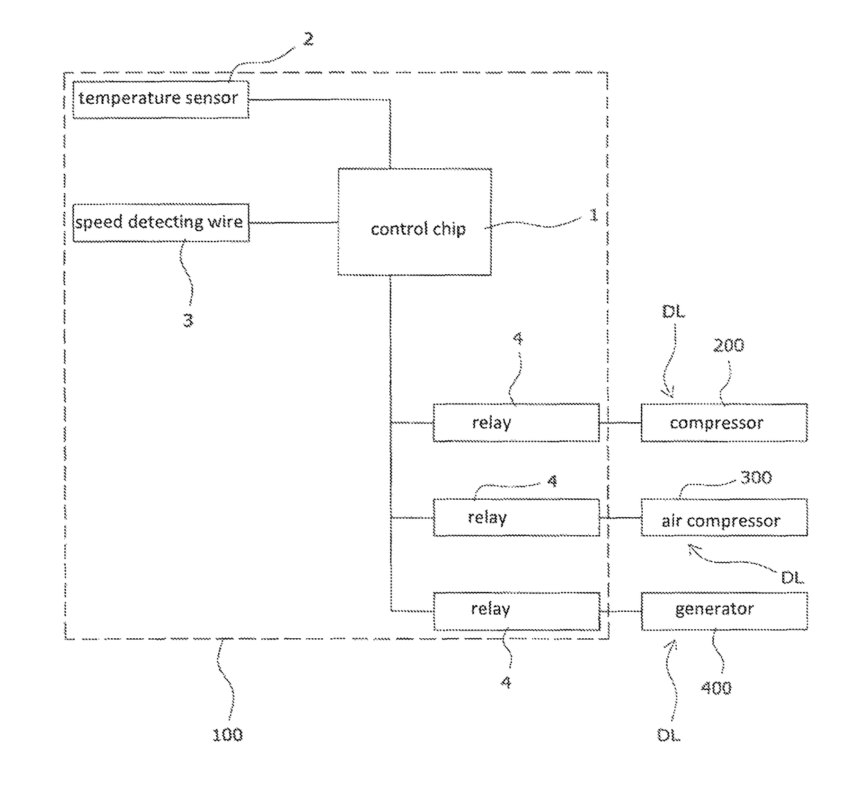
[0029]The first embodiment as shown in FIG. 3 discloses a vehicle power adjusting device (100), applied in auxiliary dynamic loads on a vehicle, comprising: a control chip (1), a temperature sensor (2) electrically connected with the control chip (1), a speed detecting wire (3) electrically connected with the control chip (1), and a relay (4) disposed correspondingly to each auxiliary dynamic load, wherein the vehicle power adjusting device (100) is an external type device for the vehicle; the temperature sensor (2) configured to sense the temperature inside the vehicle; the speed detecting wire (3) configured to detect the vehicle speed; the relay (4) configured to start and close the auxiliary dynamic loads; when the vehicle starts moving or accelerates, or an throttle is increased, the control chip (1) can obtain the vehicle speed and temperature through the temperature sensor (2) and the speed detecting wire (3), and control operation of the relay (4) through a predetermined pro...

second embodiment

[0043]The second embodiment as shown in FIG. 4A discloses a vehicle power adjusting device (100), applied in auxiliary dynamic loads on a vehicle, comprising: a control chip (1) electrically connected with the auxiliary dynamic loads, a temperature sensor (2) electrically connected with the control chip (1), a speed detecting wire (3) electrically connected with the control chip (1), a relay (4) disposed correspondingly to each auxiliary dynamic load, a control panel (5), and a control switch (6); wherein the vehicle power adjusting device (100) is an internal type device on the vehicle; the temperature sensor (2) configured to sense the temperature inside the vehicle; the speed detecting wire (3) configured to detect the vehicle speed; the control panel (5) disposed inside the vehicle for controlling operation of the vehicle; the control switch (6) disposed on the control panel (5) for controlling operation of the vehicle power adjusting device (100); the relay (4) configured to st...


PUM


Abstract

A vehicle power adjusting device, applied in auxiliary dynamic loads on a vehicle comprises a control chip, a temperature sensor, a speed detecting wire, and a relay; when the power for starting the vehicle is insufficient, auxiliary dynamic load is closed to release power, such that the power for starting is sufficient, so as to decrease the accelerating time, reduce toxic emission and enable the auxiliary dynamic load by using the surplus power during the cruising vehicle and the wasted power during the decelerating vehicle, thereby achieving the purpose of reducing the energy consumption, having powerful starting, completing combustion, reducing exhaust gas, and also saving fuel, reducing carbon emission and protecting environment effects.

Description

CROSS-REFERENCE TO RELATED APPLICATION[0001]This application claims priority from International Application No. PCT / CN2014 / 086208, filed 10 Sep. 2014, the contents of which are hereby incorporated by reference in their entirety for all purposes.FIELD OF THE INVENTION[0002]The present invention relates to a vehicle power adjusting device, particularly to a vehicle power adjusting device applied with auxiliary dynamic loads on a vehicle.BACKGROUND OF THE INVENTION[0003]Vehicle power generated by a motor or an engine is mainly transmitted to tires to make the vehicle moving forward, and is secondly transmitted to auxiliary dynamic loads, such as a compressor of an air-conditioning system, an air compressor, and a generator, however, the power will be reduced about 15%-20% for the engine while transmitting to the auxiliary dynamic load, and power will be reduced more, even if driving in the city.[0004]The power used in vehicle as shown in FIG. 1 can be mainly divided into three conditio...

Claims


Application Information

Patent Timeline
Patent Type & Authority Patents(United States)
IPC IPC(8): B60H1/32
CPCB60H1/3208B60H2001/3273B60H2001/3266B60H2001/3261
Inventor LU, JUI-HSUAN
Owner ATALI TECH
Why Eureka
Try Eureka