
Always-on lighting device having multiple power controllers and control method thereof

a technology of power controllers and lighting devices, applied in the direction of electrical equipment, energy saving control techniques, etc., can solve the problems of reducing service life, lighting devices may still be damaged, and light devices tend to be damaged

Active Publication Date: 2022-11-15
XIAMEN PVTECH
View PDF1 Cites 0 Cited by
  • Summary
  • Abstract
  • Description
  • Claims
  • Application Information

AI Technical Summary

Benefits of technology

The always-on lighting device with multiple power controllers described in this patent has several advantages. First, the devices have multiple light sources that can be turned on in a rotating pattern, which helps to extend their lifespan. Second, the device can adjust its mode of operation based on changes in environmental factors, reducing the chances of damage to the light sources and keeping them in good condition for a longer time. Third, the device can switch between a master control mode and an alternate mode, or adjust the brightness of the light sources, saving energy and better meeting actual requirements.

Problems solved by technology

However, the lighting devices tend to be damaged if the lighting devices have been in on state for a long period of time, which will reduce the service lives thereof.
However, these lighting devices may still be damaged due to various environmental factors (high outdoor temperature, weather, direction of sunlight, etc.) even if the lighting systems turn on these lighting devices by turns, which cannot satisfy the actual requirements of these buildings.

Method used


Image

  • Always-on lighting device having multiple power controllers and control method thereof
  • Always-on lighting device having multiple power controllers and control method thereof
  • Always-on lighting device having multiple power controllers and control method thereof

Examples


Embodiment Construction

[0021]In the following detailed description, for purposes of explanation, numerous specific details are set forth in order to provide a thorough understanding of the disclosed embodiments. It will be apparent, however, that one or more embodiments may be practiced without these specific details. In other instances, well-known structures and devices are schematically shown in order to simplify the drawing. It should be understood that, when it is described that an element is “coupled” or “connected” to another element, the element may be “directly coupled” or “directly connected” to the other element or “coupled” or “connected” to the other element through a third element. In contrast, it should be understood that, when it is described that an element is “directly coupled” or “directly connected” to another element, there are no intervening elements.

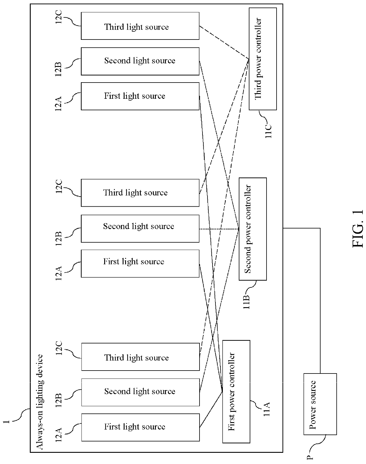
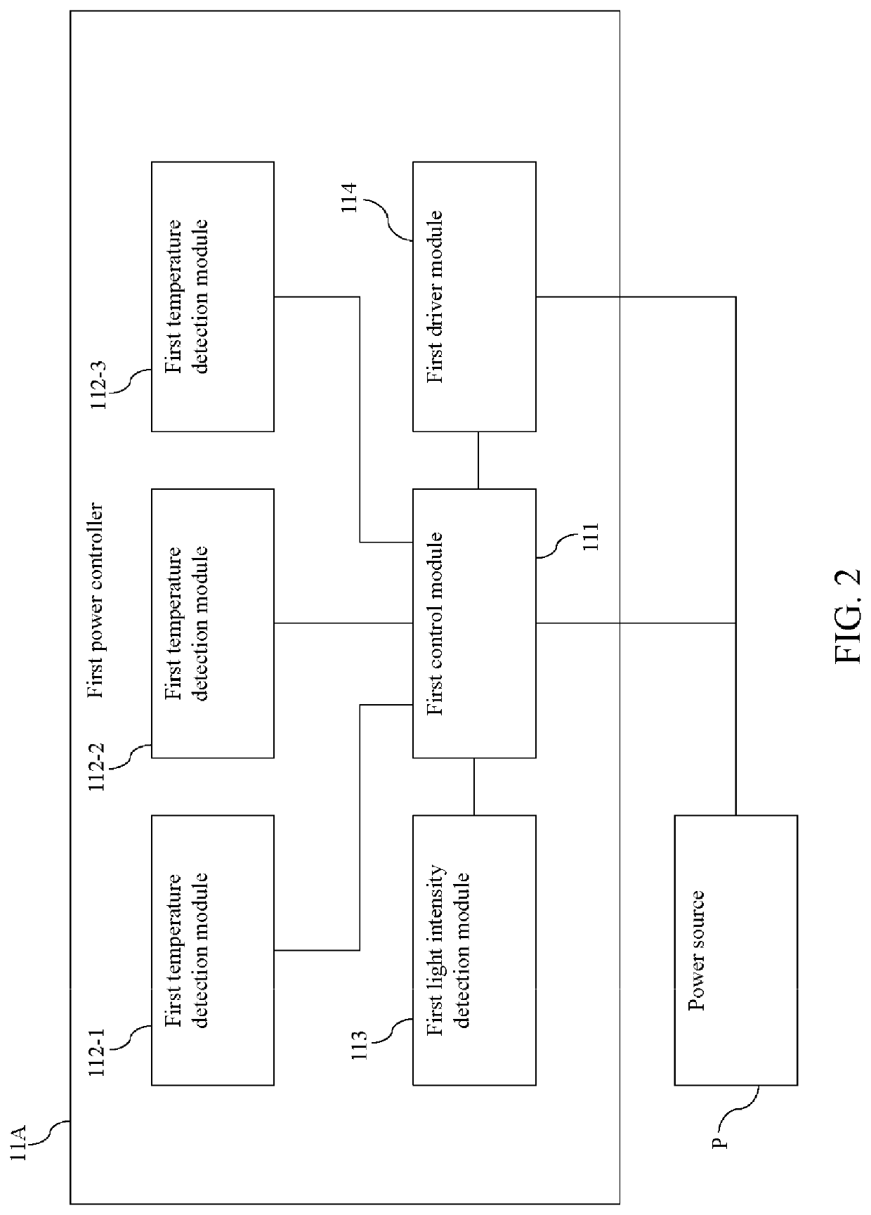
[0022]Please refer to FIG. 1 and FIG. 2. FIG. 1 is a block diagram of an always-on lighting device in accordance with one embodiment of ...


PUM


Abstract

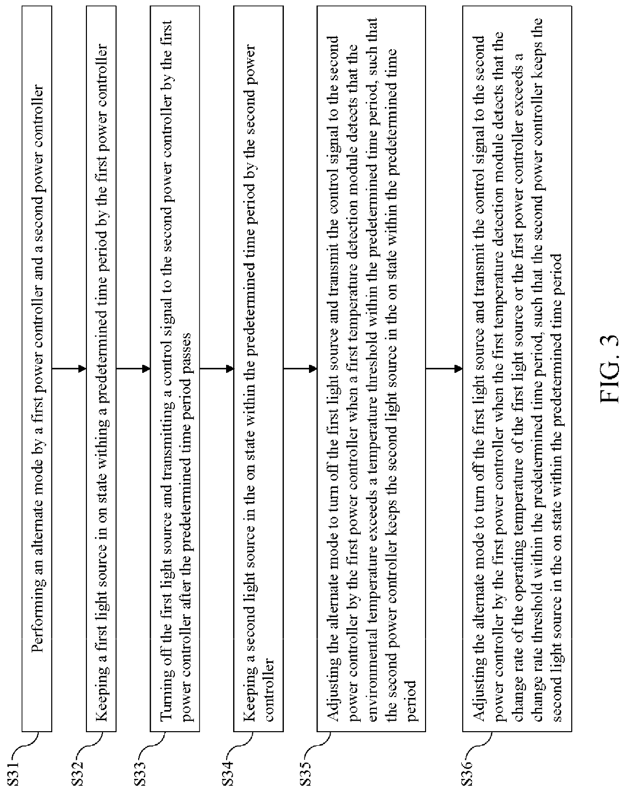
An always-on lighting device having multiple power controllers is provided, which includes a first power controller, a first light source, a second power controller and a second light source. The first power controller and the second power controller execute an alternate mode. In the alternate mode, the first power controller keeps the first light source in on state within a predetermined time period. Then, the first power controller turns off the first light source after the predetermine time period passes and transmits a control signal to the second power controller, such that the second power controller keeps the second light source in on state within the predetermined time period.

Description

BACKGROUND OF THE INVENTION1. Field of the Invention[0001]The present invention relates to a lighting device, in particular to an always-on lighting device having multiple power controllers. The present invention further relates to the control method of the lighting device.2. Description of the Prior Art[0002]Some buildings (e.g., train stations, high speed rail stations, airports, etc.) should be operating 24 hours a day, so the lighting devices thereof need to always be turned on. However, the lighting devices tend to be damaged if the lighting devices have been in on state for a long period of time, which will reduce the service lives thereof. Accordingly, the lighting systems of these buildings may turn on these lighting devices by turns. However, these lighting devices may still be damaged due to various environmental factors (high outdoor temperature, weather, direction of sunlight, etc.) even if the lighting systems turn on these lighting devices by turns, which cannot satisf...

Claims


Application Information

Patent Timeline
Patent Type & Authority Patents(United States)
IPC IPC(8): H05B47/11
CPCH05B47/11Y02B20/40H05B45/18H05B45/56H05B47/28H05B47/155H05B47/16
Inventor LU, FUXINGLIU, RONGTUYE, HAO
Owner XIAMEN PVTECH
Learn More