Interactive dispensing bottle cap

a bottle cap and bottle technology, applied in the field of bottle caps, can solve the problems of rapid degradation the harsh effect of aspirin on the stomach lining, and the use of aspirin, and achieve the effect of facilitating the release and mixing of the contents of the bottle cap

Inactive Publication Date: 2018-05-22
DVORAK MARY LISA
View PDF12 Cites 5 Cited by
  • Summary
  • Abstract
  • Description
  • Claims
  • Application Information

AI Technical Summary

Benefits of technology

[0024]When the end user / consumer twists the upper cap in a first (e.g., clockwise) direction, the outer cap spins in a downward track (formed by a J-channel) and the cutter tip located therein pierces an unobstructed opening into a sealing membrane situated in the lower section of the cap. The bottle product may then be shaken, if desired, to thoroughly mix the additives (released from the cap reservoir) into the liquid in the bottle. The upper cap then locks into a second (counter-clockwise) mode, permitting the consumer to remove the entire cap assembly and to consume or to use, as appropriate, the mixture.
[0025]New features of the present disclosure include: a c-clip holding guide pins that follow the J-channel; reduction of J-channel elements to two locations rather than three locations as described in the inventor's prior U.S. Pat. No. 7,614,496; a filler port opening at the top of the upper cap; a separate cutter core and filler port plug; a cut-away section of the cutter core cylinder to facilitate release and mixing of cap contents; a clear plastic (when preferred) upper cap; an additional lower “lobe” of the J-channel to permit locking, unscrewing, removal and subsequent re-closure of the cap onto the bottle. Shrink-labelling the assembled filled cap can also be achieved.

Problems solved by technology

One drawback in the use of aspirin is its harsh effect on the stomach lining.
Unfortunately, the most commonly used forms of aspirin rapidly degrade in aqueous solution.
For many active people, this is inconvenient.
Unfortunately, the same kind of difficulty is encountered in using this compartment, in that the user accesses the contents of the compartment, and then if it is to be dissolved in water in the dispenser, then it must be poured into the dispenser much as the packet of power is poured in.
Dispensing cap technologies currently exist on the market despite their comparative drawbacks: very limited “payload” capacity, difficulties in permitting free-flow and thorough mixing of the cap contents and bottled liquid, logistical constraints on production line efficiency.

Method used


Image

  • Interactive dispensing bottle cap
  • Interactive dispensing bottle cap
  • Interactive dispensing bottle cap

Examples


Embodiment Construction

[0108]Reference is now made to the drawings, which depict preferred embodiments of the present invention, but are not drawn to scale.

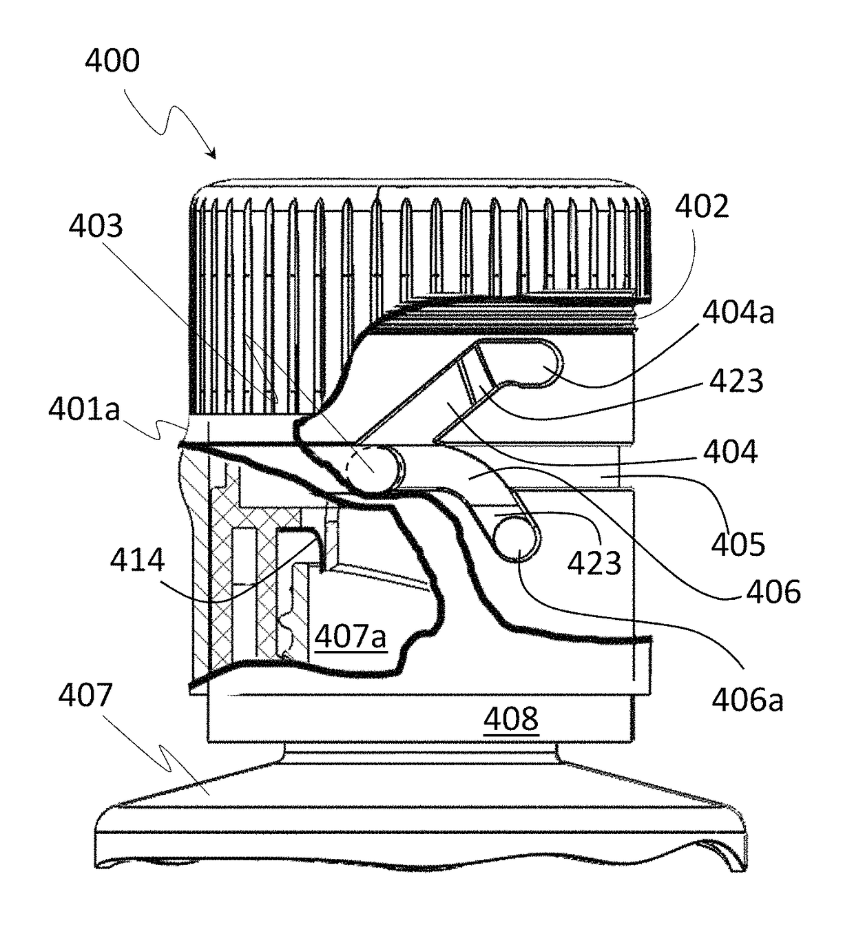
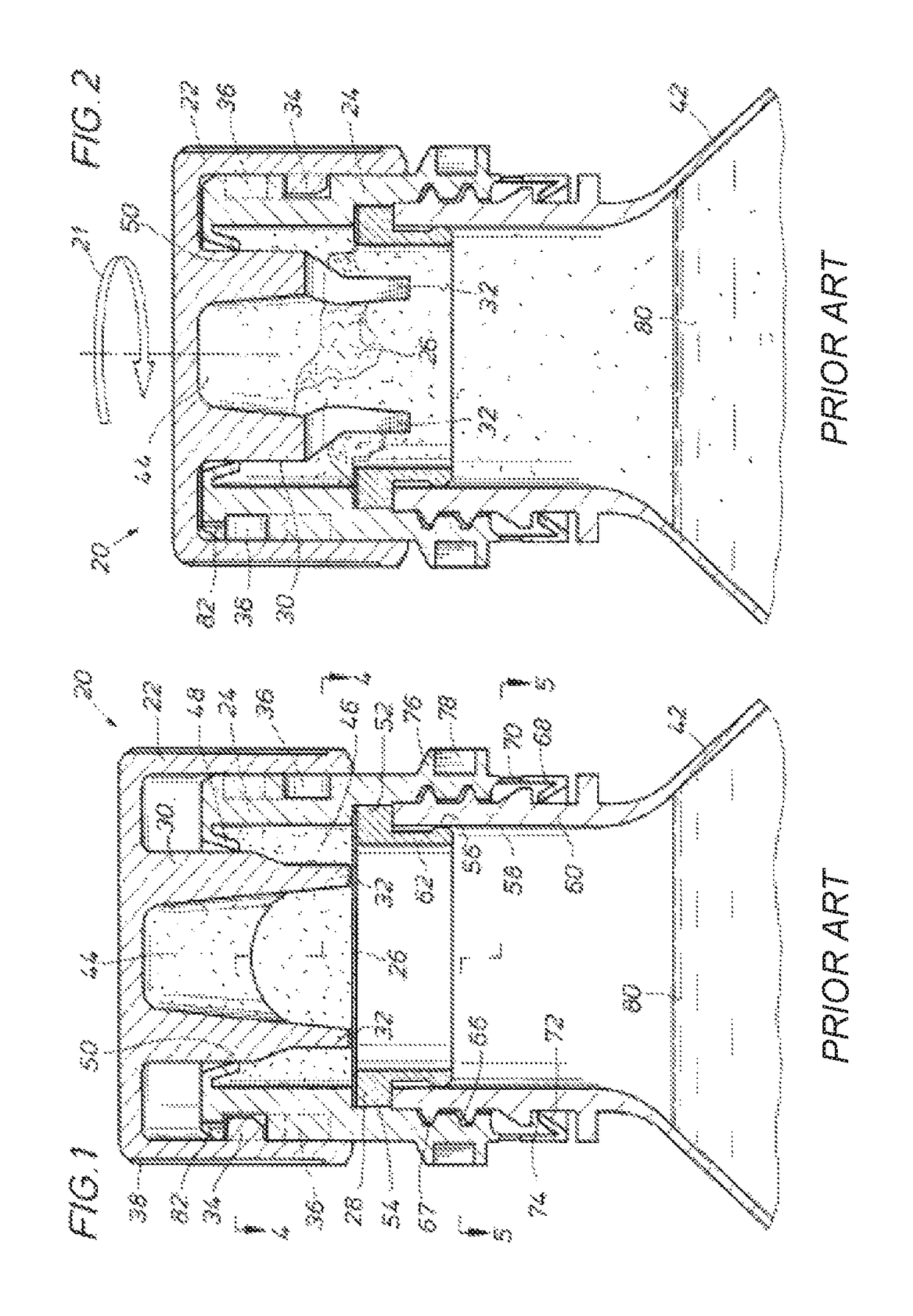
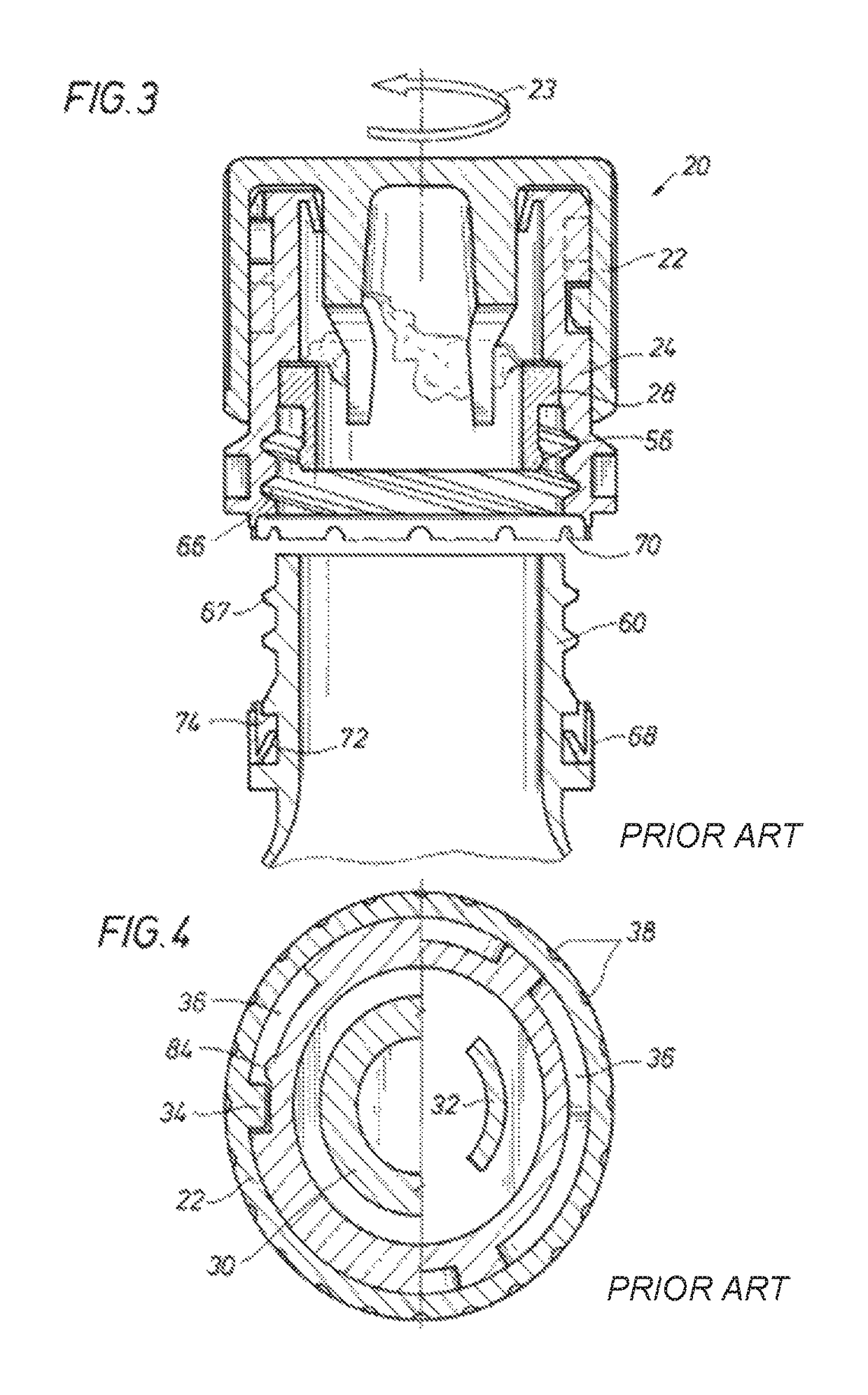
[0109]Referring to the inventor's U.S. Pat. No. 7,614,496, FIG. 1 depicts a bottle cap 20 defining a dispenser of an analgesic in accordance with the teachings of the present invention. The cap 20 primarily comprises an outer cap 22, an inner cap 24, a membrane 26 adjoining the inner cap 24, and a seal ring 28. The outer cap 22 has an inner concentric barrel 30 which is equipped with two downwardly extending protrusions or teeth 32 and three inwardly extending protrusions 34, which are shown and described below also in respect of FIG. 4. Inwardly extending protrusions 34 engage opposing J-shaped slots 36 (See FIG. 4 and FIG. 6). The outer surface of outer cap 22 is provided with a plurality of laterally extending grooves 38, providing a gripping surface on the outside of the outer cap 22. The barrel 30 is hollow to provide a chamber or cavity 44 for th...


PUM


Abstract

A bottle cap is adapted to retain a quantity of an additive, such as, e.g., aspirin, vitamins, nutritional supplements or the like. The additive is retained in an isolated condition within a sealed chamber within the bottle cap but in fluid communication with the liquid within the bottle, such as water. A cap with at least one downward extending cutter is provided to breech the seal of the chamber, thereby releasing some, or all, of the additive retained within the bottle cap. The cap comprises an outer cap member installed over a lower cap member in rotational sealed relationship. A penetrable membrane is located at the lower portion of the lower cap to define a storage chamber for holding a desired additive. A modified J-channel governs movement of the outer cap relative to the inner cap to cause the cutter to move downward and pierce the membrane.

Description

CROSS REFERENCES TO RELATED APPLICATIONS[0001]This application claims the benefit of the filing date of, and priority to, U.S. Provisional Patent Application No. 61 / 921,098, entitled “Interactive Dispensing Bottle Cap”, filed Dec. 27, 2013, which application is incorporated herein by reference in its entirety.STATEMENT REGARDING FEDERALLY SPONSORED RESEARCH OR DEVELOPMENT[0002]Not Applicable.BACKGROUND OF THE INVENTIONField of the Invention[0003]The present invention is directed to bottle caps capable of containing liquids, powders or other dissolvable substances, including, for example, nutritional supplements, vitamins, analgesics, or other substances desired for later dispensing into the contents of the bottle.Background Art[0004]In the inventor's commonly owned U.S. Pat. No. 7,614,496, there are disclosed exemplary dispensing bottle cap designs. The entirety of U.S. Pat. No. 7,614,496 is incorporated herein by reference.[0005]As set out in U.S. Pat. No. 7,614,496, aspirin is the...

Claims


Application Information

Patent Timeline
Patent Type & Authority Patents(United States)
IPC IPC(8): B65D81/32B65D51/28
CPCB65D81/3211B65D51/28B65D51/2835B65D81/32
Inventor DVORAK, STEVEN G.
Owner DVORAK MARY LISA
Why Eureka
Try Eureka