System for detecting defects on an object

a technology for defects and objects, applied in the field of detecting defects on objects, can solve problems such as difficulty in knowing what grain to adop

Active Publication Date: 2018-05-22
SN DETUDE & DE CONSTR DE MOTEURS DAVIATION S N E C M A
View PDF20 Cites 5 Cited by
  • Summary
  • Abstract
  • Description
  • Claims
  • Application Information

AI Technical Summary

Benefits of technology

[0036]This is because the digital processing according to the invention is inexpensive in computing time and can therefore easily be implemented by processing means installed in an aircraft.

Problems solved by technology

Thus the current methods require making calculations that may take a not insignificant amount of time, unless particularly powerful and very expensive computers are used.
Furthermore, it is difficult to know what grain to adopt (i.e. what is the resolution of the region to be compared) when the defects that are being sought are not known.

Method used


Image

  • System for detecting defects on an object
  • System for detecting defects on an object
  • System for detecting defects on an object

Examples


first embodiment

[0125]FIG. 5 is a detection algorithm according to the invention comprising a confirmation phase according to a

[0126]The confirmation phase comprises a comparison of the differentials relating to an abnormal subdivision belonging to a last image with differentials relating to the same abnormal subdivision belonging to each of a given number of previous images of the object, the data on the previous abnormal subdivisions being recorded in a database 17 associated with the processing means.

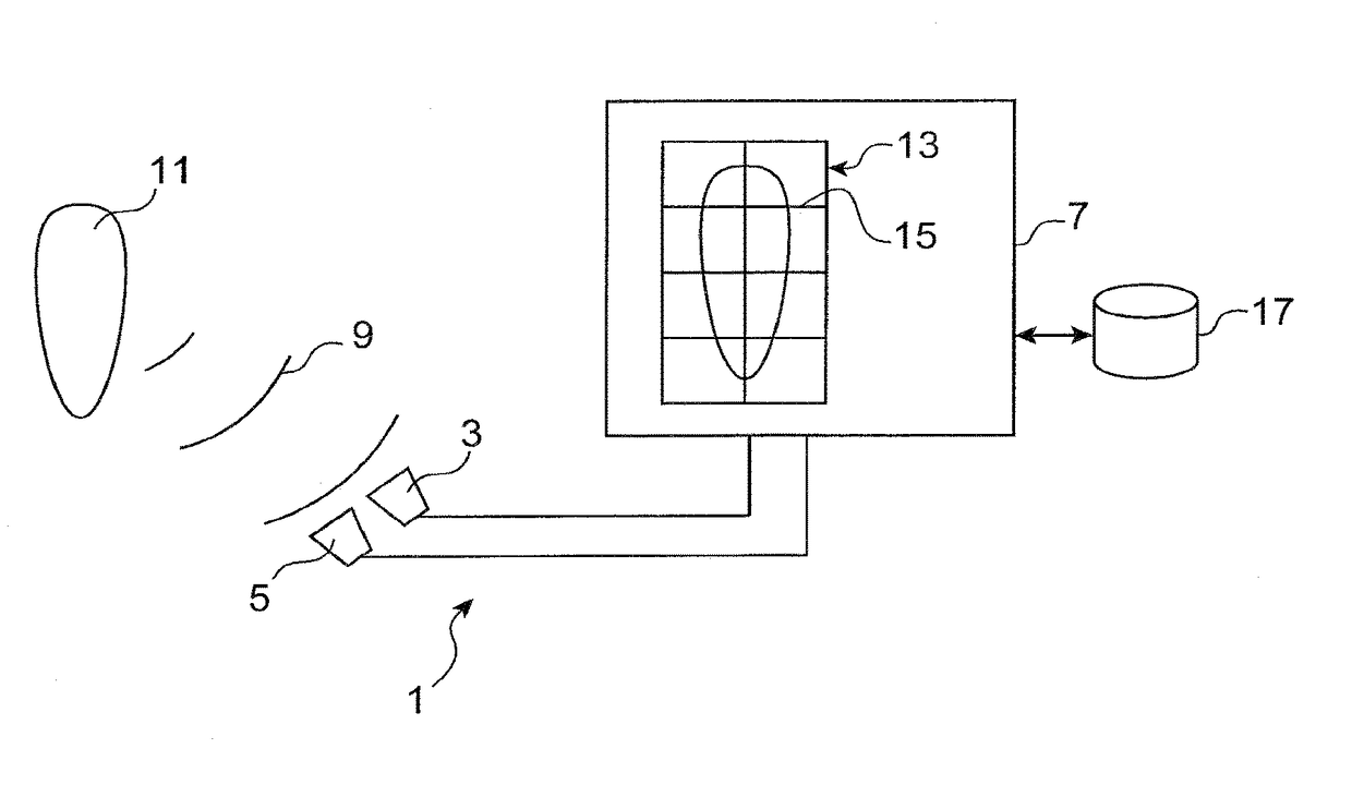
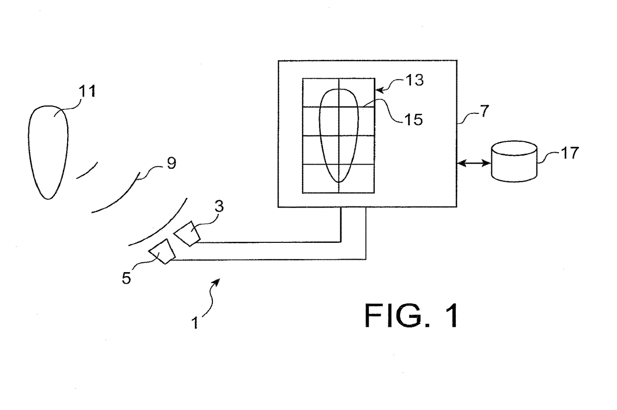
[0127]Step E21 concerns the measurement or acquisition of a physical parameter (e.g. optical, thermal or audible field) relating to the object 11, making it possible to form an image 13 of the object 11.

[0128]At step E22, the data related to the physical parameter are sent to the processing means 7.

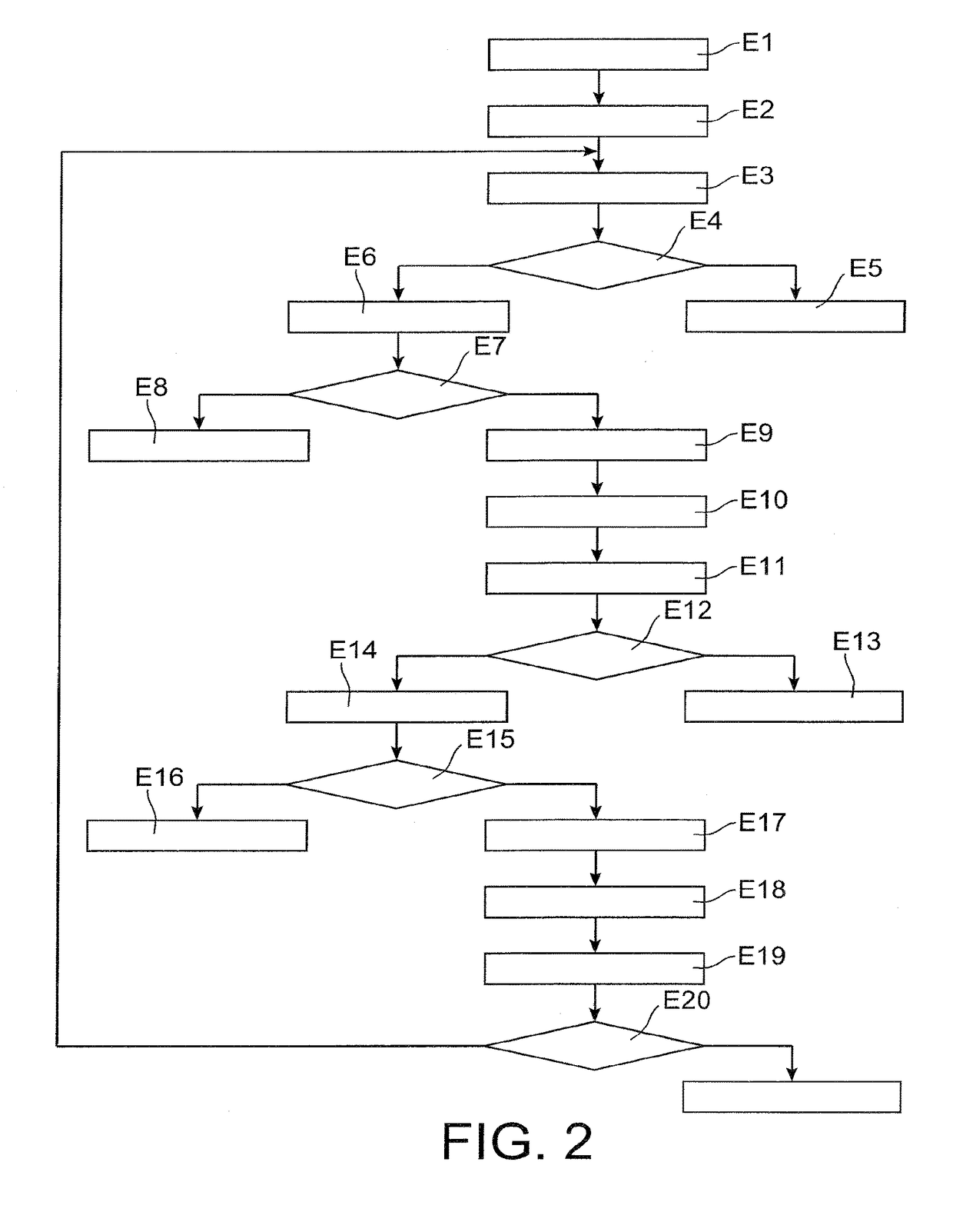
[0129]At step E23, the processing means 7 are configured so as to process the data in accordance with the flow diagram in FIG. 2.

[0130]In particular, at steps E4 and E12 (FIG. 2), it is checked whether th...

second embodiment

[0138]FIG. 6 is a detection algorithm according to the invention comprising a confirmation phase according to a

[0139]The steps of the algorithm of FIG. 6 are identical to those of FIG. 5 except for steps E32 and E33.

[0140]As before, step E31 concerns the measurement or acquisition of a physical parameter (e.g. optical, thermal or audible field) relating to the object 11 enabling an image 13 of the object to be formed. If the data correspond to a first image, then step E32 is passed to, and otherwise to step E33.

[0141]Step E32 is a learning phase during which a learning database is constructed by comparing the differentials of the subdivisions of the first image of a sound object. This may be done according to the steps of comparisons between adjacent subdivisions in the flow diagram in FIG. 2.

[0142]Thus, at step E32, a learning database recording sound differentials between various subdivisions of the original sound image are constructed, knowing that the latter is not necessarily u...


PUM

PropertyMeasurementUnit
current differentialsaaaaaaaaaa
second currentaaaaaaaaaa
sizesaaaaaaaaaa

Abstract

A system and method for detecting defects on an object including forming an image representing the object from signals relating to the object, constructing subdivisions of the image according to auto-adaptive resolutions, and calculating differentials between various subdivisions in order to detect an abnormal subdivision indicating incipient failure.

Description

TECHNICAL FIELD[0001]The present invention concerns the field of detecting defects on an object and more particularly for monitoring rotating elements of an aircraft engine.PRIOR ART[0002]There exist numerous techniques using optical or audible methods for detecting defects on an object. The advantage of these techniques is that they can be used in a non-intrusive manner.[0003]For example, in the aeronautical field, during production tests or inspections of the vanes of an engine, various non-destructive inspection techniques based on the use of thermal cameras are applied. These techniques consist of using a movable heat emitter for heating the vane and a movable thermal camera for taking an infrared image of the vane. Analysis of the image is based on a comparison of a very high number of regions of the image in order to detect defects in the blade.[0004]Thus the current methods require making calculations that may take a not insignificant amount of time, unless particularly power...

Claims


Application Information

Patent Timeline
Patent Type & Authority Patents(United States)
IPC IPC(8): G01N21/88G01N29/44G01N25/72G06T7/00G01N29/04G01J5/00G01J5/10
CPCG01N21/8851G01J5/10G01N25/72G01N29/043G01N29/4409G06T7/0004G01J5/0022G06T2207/30164G01J2005/0077G01J2005/0081G01N2021/8887G01N2291/0289G01N2291/044G01N2291/2693G01N2291/2694G06T2207/20021G01N29/4445G01J5/48
Inventor BENSE, WILLIAMGEREZ, VALERIO
Owner SN DETUDE & DE CONSTR DE MOTEURS DAVIATION S N E C M A
Why Eureka
Try Eureka