Recording method for at least two TOF cameras

Active Publication Date: 2018-05-22
BLUETECHNIX
View PDF5 Cites 7 Cited by
  • Summary
  • Abstract
  • Description
  • Claims
  • Application Information

AI Technical Summary

Benefits of technology

[0014]It is the object of the present invention to provide a method which does not have these disadvantages and which eliminates, or at least reduces, the mutual negative influence of several ToF cameras. This shall be achieved with a low need for equipment. Networking of the individual camera

Problems solved by technology

In the case of artificial light sources which are modulated in the megahertz range the suppression does not work completely and the calculated depth data are erroneous in pixels.
Wrong depth calculations in a ToF camera occurs especially when the artificial light sources of other cameras are recorded in the visual range of the own camera sensor.
In these cases, the results of the depth calculation are at least partly invalid.
These mutual disturbances lead to the consequence that the distance-related measuring results are distorted and the depth information no longer corresponds to the real conditions.
Problems in the networking of ToF cameras according to this principle arise in such a way that this approach entails considerable additional c

Method used


Image

  • Recording method for at least two TOF cameras
  • Recording method for at least two TOF cameras
  • Recording method for at least two TOF cameras

Examples


Example

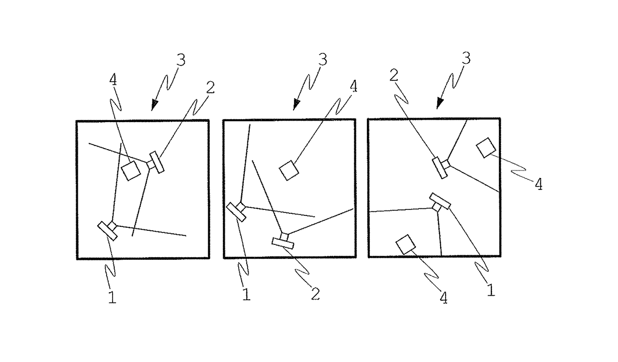
[0040]FIG. 1 shows a scene 3 consisting of objects 4 in three potential constellations, which scene is to be recorded by means of two time-of-flight cameras 1, 2. In the left constellation, the visual fields of the individual cameras 1, 2 overlap one another to a high extent. Since the cameras are situated opposite of each other, the light of the one camera is co-detected by the other camera in a direct manner, i.e. without prior reflection on an object 4. One must therefore expect a strong mutual influence of the cameras 1, 2 caused by the emitted light and therefore a strong falsification of the determined depth information.

[0041]In the constellation shown in the middle, the cameras 1, 2 do not illuminate each other directly, but reflected light of the one camera is co-detected by the respective other camera. In this case too, a mutual influence can also be expected, even though it is lower than in the left constellation. In the constellation shown on the right, the visual fields ...


PUM


Abstract

The invention relates to a method for recording a scene (3) using at least two time-of-flight cameras (1, 2), which respectively comprise a light source (5) and an image sensor (6), wherein image recording operations which comprise a measuring operation for determining depth information are carried out using each of the at least two time-of-flight cameras (1, 2), wherein the measuring operation comprises the emission of modulated light (11) by the light source (5), the detection of modulated light (12) after the reflection on objects (4) of the scene (3) using the image sensor (6), and the calculation of depth information from the propagation time of the modulated light between the emission and the detection.
In order to increase the image quality, a first time-of-flight camera (1) uses the measurement results of the measuring operation carried out by said camera to determine the extent to which modulated light from a second time-of-flight camera (2) was also detected in this measuring operation in addition to the light (11) emitted by its own light source (5), and the first time-of-flight camera (1) changes the recording mode thereof on the basis of the result of this determination.

Description

CROSS-REFERENCE TO RELATED APPLICATIONS[0001]This is a National Phase application of PCT / EP2013 / 068818 filed Sep. 11, 2013, which claims priority to AT A1191 / 2012 filed Nov. 8, 2012, all of which are herein incorporated by reference therein in their entireties.BACKGROUND OF THE INVENTION[0002]The invention relates to a method for recording a scene using at least two time-of-flight cameras, which respectively comprise a light source and an image sensor, wherein image recording operations which comprise a measuring operation for determining depth information are carried out using each of the at least two time-of-flight cameras, wherein the measuring operation comprises the emission of modulated light by the light source, the detection of modulated light after the reflection on objects of the scene using the image sensor, and the calculation of depth information from the propagation time of the modulated light between the emission and the detection.[0003]Time-of-flight (ToF) cameras co...

Claims


Application Information

Patent Timeline
IPC IPC(8): G01S17/36G01S17/10G01S7/487G01S17/89G01S17/26G01S17/894
CPCG01S17/36G01S17/89G01S17/102G01S7/487H04N13/20H04N7/18G01S17/894G01S17/26
Inventor OBERHAMMER, ROLANDHRANITZKY, ROBERT
Owner BLUETECHNIX
Why Eureka
Try Eureka