
Organic light emitting display panel and display apparatus

a technology of light-emitting display panel and display apparatus, which is applied in the direction of organic semiconductor devices, semiconductor devices, diodes, etc., can solve the problems of low aperture ratio, affecting display effect, affecting display brightness, etc., and achieves high resistance, effective reduction of voltage drop, and increase of electrical conductivity of cathodes

Active Publication Date: 2018-05-22
BOE TECH GRP CO LTD
View PDF18 Cites 6 Cited by
  • Summary
  • Abstract
  • Description
  • Claims
  • Application Information

AI Technical Summary

Benefits of technology

[0009]In view of the above and other deficiencies in the prior art, the embodiments of the present invention provide an organic light emitting display panel and a display apparatus, in which a cathode has an increased electrical conductivity, thereby effectively reducing voltage drop due to a extremely thin cathode.
[0010]According to a further aspect of the embodiments of the present invention, there is provided an organic light emitting display panel and a display apparatus, which may improve display uniformity.
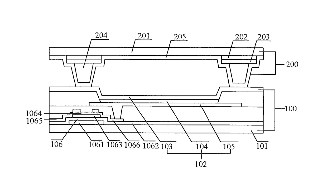
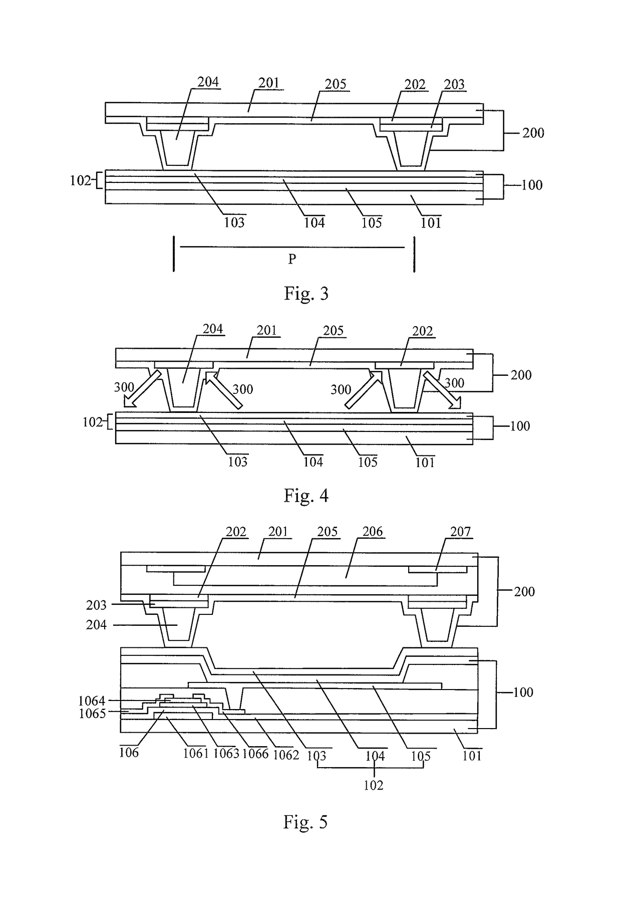
[0030]According to the organic light emitting display panel provided in the above various embodiments of the present invention, the auxiliary electrode is provided in the second substrate, and electrically connected to the cathode. As a result, it increases the electrical conductivity of the cathode, thereby effectively reducing the voltage drop caused by the extremely thin cathode and the extremely high resistance, and improving the display uniformity. In comparison to the conventional organic light emitting display panel, in which an auxiliary electrode is provided on a first substrate having a complicated structure and produced through a large number of processes, the auxiliary electrode provided on the second substrate may prevent producing process of the auxiliary electrode from damaging the organic light emitting diode in the first substrate, thereby improving overall good quality rate of the organic light emitting display panel. Furthermore, since the antireflection layer is formed on the auxiliary electrode, it may absorb light rays emitted onto the auxiliary electrode, and reduce light leakage between the pixels caused by reflection of the auxiliary electrode, thereby improving contrast ratio of the display.
[0031]When the organic light emitting display panel is applied to the display apparatus, the provision of the auxiliary electrode may reduce the voltage drop of the display apparatus caused by the extremely thin cathode and the extremely high resistance, make the display apparatus have excellent display uniformity. In addition, since the antireflection layer is formed on the auxiliary electrode, it may absorb light rays emitted onto the auxiliary electrode, and reduce light leakage between the pixels caused by reflection of the auxiliary electrode, thereby improving the display contrast ratio of the display apparatus.

Problems solved by technology

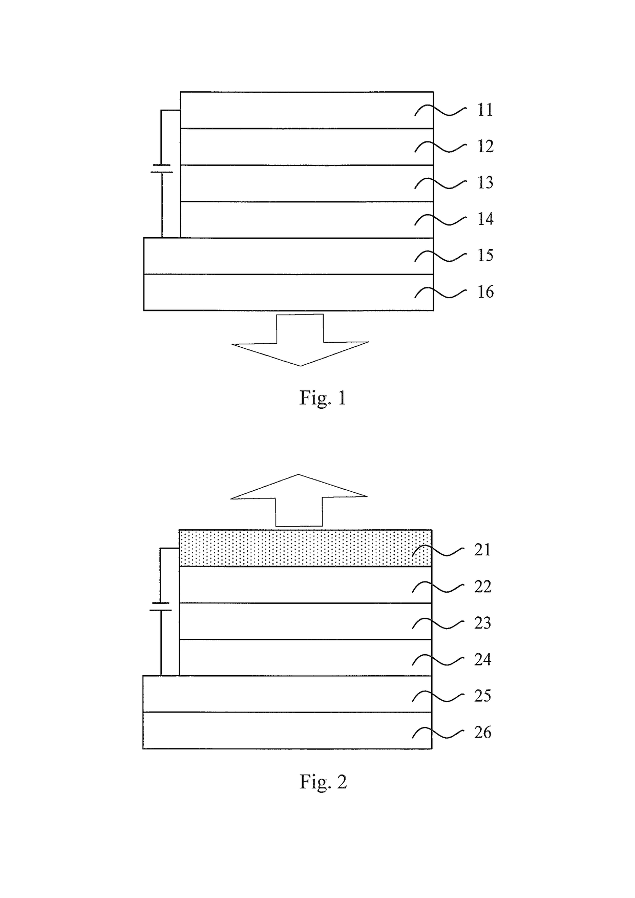
However, such device has a complicated OLED pixel driving circuit, typically requiring at least two thin film transistors (TFT) and one capacitor, as a result, a majority of light is wasted due to obstruction of the TFT and various electrodes, thereby causing a very low aperture ratio, for example, the light emitted out of the panel in the bottom-emitting device is typically approximately 30-50% of the light emitted from the light emitting layer.
As a kind of transparent electrically conductive material, ITO may reduces light loss in the top emitting process, however, such material has related disadvantages, such as high resistance, complicated sputter process and damage to the organic layer derived from the sputter process, thus affecting display effect.
Too thick metal cathode may reduce the transmittance of the device, further affect the display brightness, thereby increasing power consumption for displaying.
Based on this, the metal cathode in the top-emitting device is generally provided to be relatively thinner, however, an overall resistance of the thin metal cathode is extremely large, it therefore leads to a relatively high voltage drop.
Particularly, the voltage drop across the cathode increases significantly with the increase of dimension thereof, thereby incurring a non-uniform image quality and display characteristic.

Method used


Image

  • Organic light emitting display panel and display apparatus
  • Organic light emitting display panel and display apparatus
  • Organic light emitting display panel and display apparatus

Examples


Embodiment Construction

[0039]The present invention will be further described in detail below, in combination with the accompanying figures and the detailed implementations, in order that the technical solutions of the present invention are better understood by the person skilled in the art. Obviously, the described embodiments are merely a part of all embodiments, rather than all of embodiments. All of the other embodiments obtained by the person skilled in the art without creative effort fall into the scope of the present invention.

[0040]In addition, in the following detailed description, for purposes of description, a number of specific details are explained to provide a comprehensive understanding to the embodiments of the present disclosure. However, it is obvious that one or more embodiments may be implemented without these specific details. In other cases, conventional structures and devices are shown in schematic diagrams to simplify the drawings.

[0041]Now it is necessary to provide the following e...


PUM


Abstract

The present disclosure relates to an organic light emitting display panel and a display apparatus. The organic light emitting display panel includes: a first substrate provided with a plurality of pixels each comprising an organic light emitting diode; a second substrate having at least one auxiliary electrode electrically connected to a cathode of the organic light emitting diode, each auxiliary electrodes being located on a side of the second substrate facing the first substrate and corresponding to a gap between adjacent pixels on the first substrate; and an antireflection layer formed on the auxiliary electrode for absorbing light rays directed to the auxiliary electrode. In the present disclosure, by the auxiliary electrode formed on the second substrate and electrically connected to the cathode on the first substrate, the voltage drop of the cathode may be significantly reduced, and the uniformity of the display brightness is improved. Meanwhile, by the antireflection layer formed on the auxiliary electrode, light leakage phenomenon due to reflection of a metal auxiliary electrode may be prevented, thereby improving contrast ratio of the display.

Description

CROSS-REFERENCE TO RELATED APPLICATION[0001]This Application is a Section 371 National Stage Application of International Application No. PCT / CN2014 / 076136, filed 24 Apr. 2014 and published as WO 2015 / 100885 on 9 Jul. 2015, in Chinese, the contents of which are hereby incorporated by reference in their entirety.BACKGROUND OF THE INVENTION[0002]Field of the Invention[0003]Embodiments of the present invention relate to a display apparatus, in particular, to an organic light emitting display panel for a display apparatus and a display apparatus.[0004]Description of the Related Art[0005]An organic light emitting display panel is a new type of flat-panel display apparatus, which has many advantages, such as active emission, high brightness, ultrathin thickness, low power consumption, wide angle of view, wide operating temperature range, and the like.[0006]In the organic light emitting display panel, an organic electroluminescent device (OLED) may be divided into two types, i.e., bottom-e...

Claims


Application Information

Patent Timeline
Patent Type & Authority Patents(United States)
IPC IPC(8): H01L51/52H01L27/32
CPCH01L51/5228H01L27/322H01L27/3211H01L51/5284H01L51/525H01L2251/5315H10K59/38H10K50/824H10K50/8428H10K50/865H10K59/35H10K2102/3026
Inventor SHEN, WULINWANG, DONGFANGCHEN, HAIJING
Owner BOE TECH GRP CO LTD
Learn More