Method and apparatus for surface treatment of roll

a surface treatment and roll technology, applied in the direction of other domestic objects, manufacturing equipment/tools, manufacturing tools, etc., can solve the problems of uneven thickness of solidified shell, cracks or folding defects on the surface of cast strips, and easy wear of edge dams through repeated contact and friction, etc., to achieve quick and easy surface treatment

Active Publication Date: 2018-05-29
POHANG IRON & STEEL CO LTD
View PDF22 Cites 0 Cited by
  • Summary
  • Abstract
  • Description
  • Claims
  • Application Information

AI Technical Summary

Benefits of technology

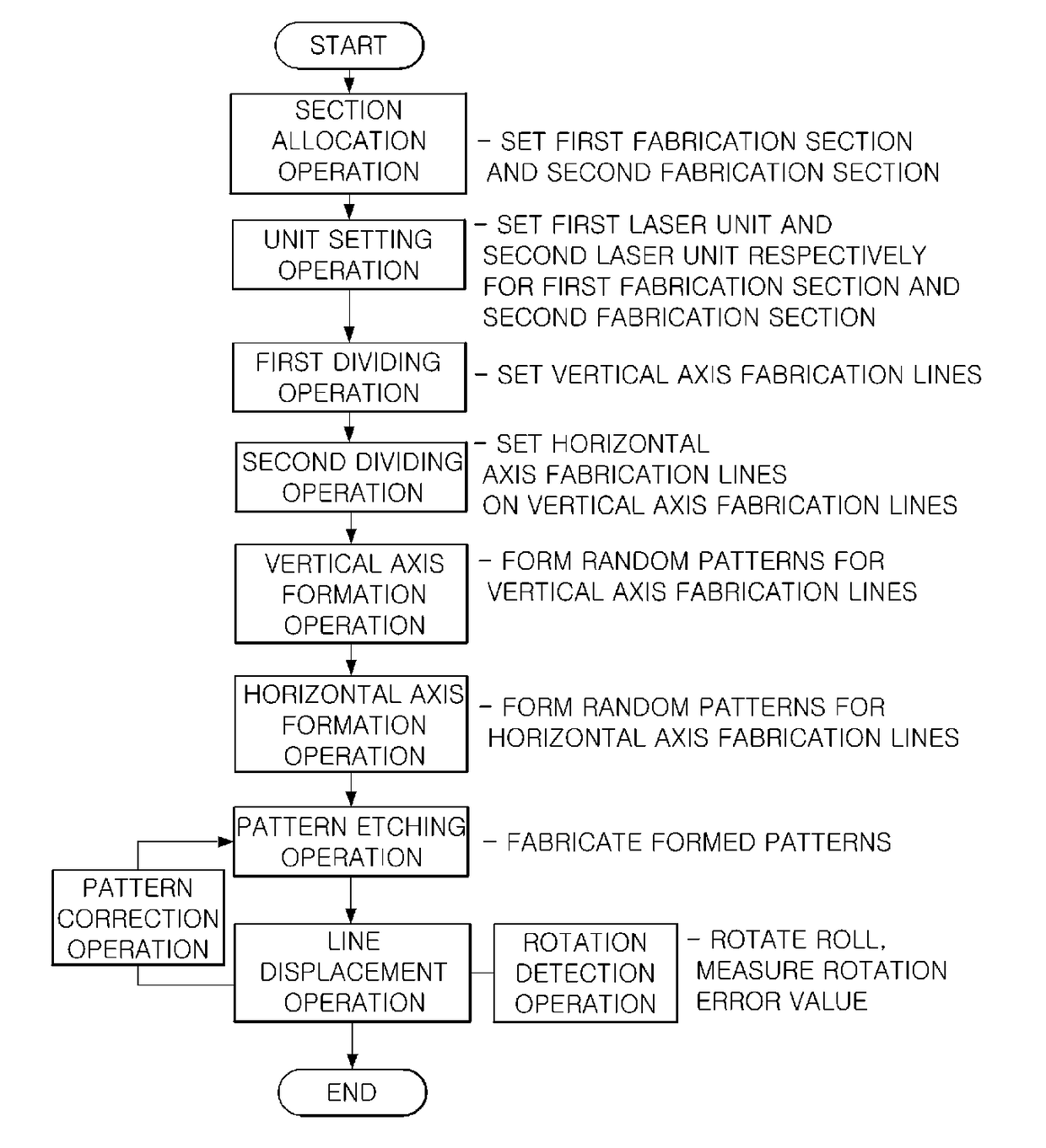
[0018]The present invention is devised to overcome such limitations as given above, and an object of the present invention is to provide a method and apparatus for surface treatment of a roll which uses a laser to quickly and easily perform surface treatment on the roll, and specifically a casting roll.
[0020]Furthermore, an objective is to provide a method and apparatus for surface treatment of the roll, by which a random pattern for preventing initial fracture and occurrences of surface defects during a subsequent operation in the strip which is fabricated through casting rolls is formed, and the pattern thus formed may be rapidly fabricated.
[0023]Thus, an objective is not only to prevent defects on the strip which is obtained by the casting rolls, but also to reduce the time taken for surface treatment of the roll, so that quality, workability, and productivity may all be improved.

Problems solved by technology

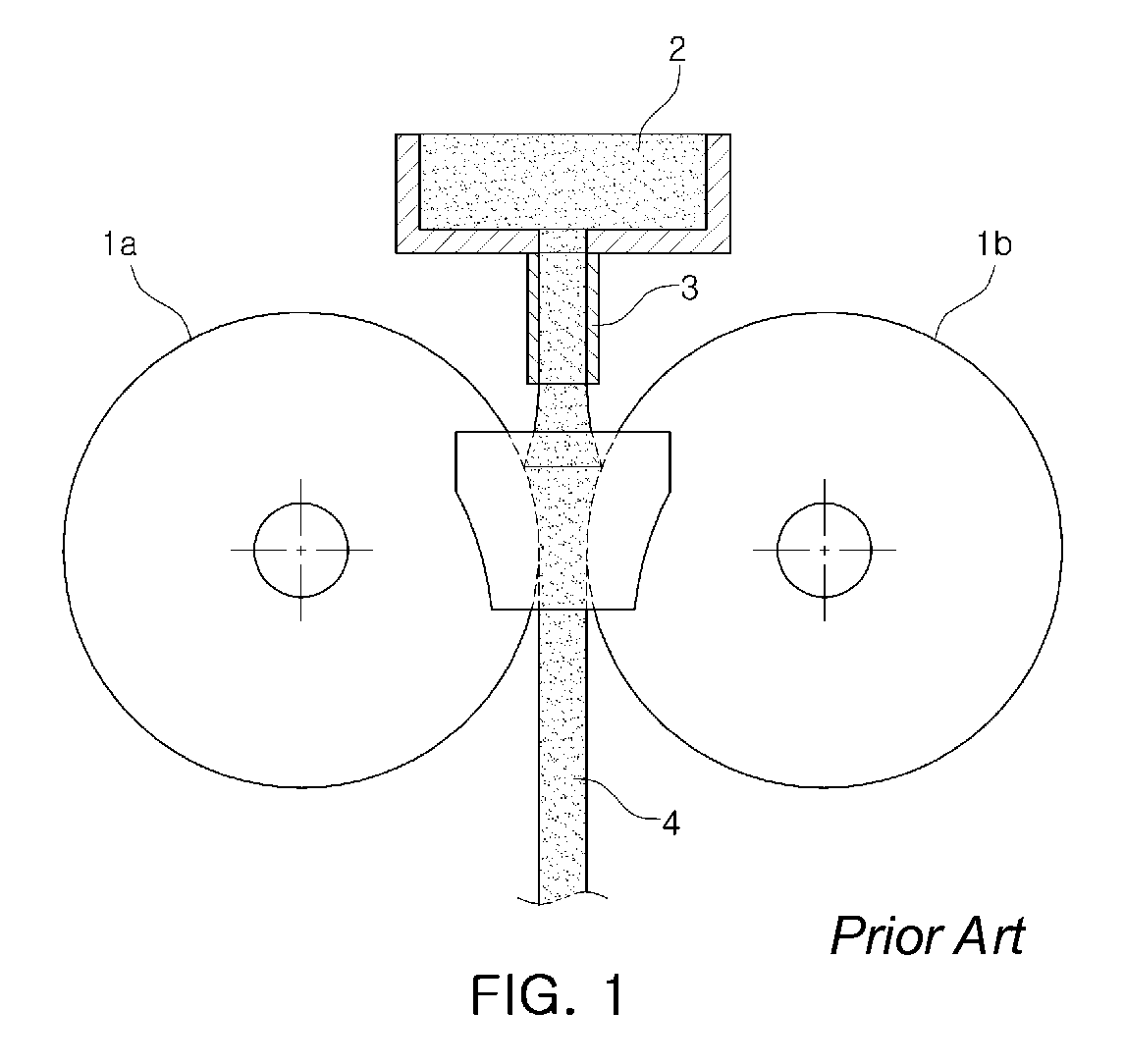
However, the edge dam may be easily worn through repeated contact and friction with the rolls 1a and 1b which are continuously rotating at a rapid rate.
However, since the contact time between the molten steel 2 and the rolls 1a and 1b is extremely short, the thickness of the solidified shell becomes non-uniform, and thus defects such as cracks or folding defects are formed on the surface of the cast strip.
In this case, a subsequent rolling operation is negatively affected, and the surface quality of a final product may be degraded so that the value as a product declines.
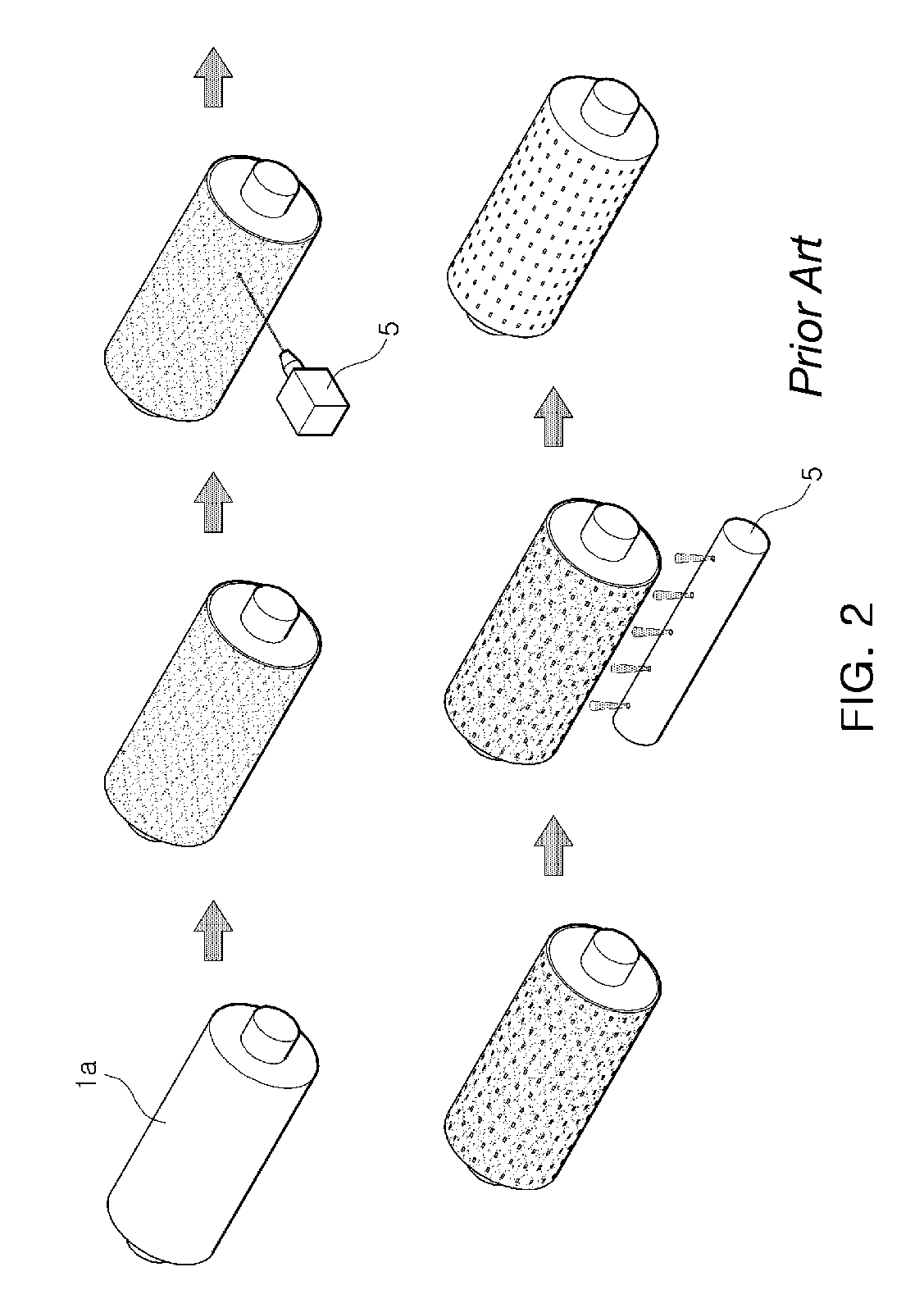
Moreover, random patterns which follow a direction along the width of the roll cannot be connected, and thus there comes to be a limit on possible forms of the dimples which can be formed on the roll surface.
Moreover, when a vision system is used to realize precision in formation by a laser, the rolls must be stopped, which causes the operating time to be unnecessarily increased.
Such an excess in operating time makes it difficult to optimize a patterning operation for each steel type, and thus there is no choice but to perform fabrication of a simple pattern, in which a simple shape is repeated, in order to reduce the operating time.
Since initial solidification conditions cannot be controlled through such a simple pattern, numerous strip fractures initially occur.
In addition, even if casting continues, there is a limitation of being unable to prevent an adhesive phenomena, dent-type defect phenomena, etc., from occurring on the product surface.

Method used


Image

  • Method and apparatus for surface treatment of roll
  • Method and apparatus for surface treatment of roll
  • Method and apparatus for surface treatment of roll

Examples


Embodiment Construction

[0056]In order to assist in understanding exemplary embodiments of the present invention, like reference numerals will refer to like elements in the accompanying drawings, and in each embodiment, a part which is related to a part having a similar effect will have a like reference numeral or an extension thereof.

[0057]Moreover, in order to clearly describe the essential feature of the present invention, descriptions of those elements and technologies which are generally known from the related art will not be provided herein, and hereinafter, the present invention will be described in detail with reference to the accompanying drawings.

[0058]However, the concept of the present invention is not limited by the following embodiments, and forms thereof in which specific parts are extended, modified, or omitted may be proposed by a person with ordinary skill in the art, and thus will be understood as being within the scope of the inventive concept.

[0059]First, in an exemplary embodiment, a ...


PUM

PropertyMeasurementUnit
heightaaaaaaaaaa
heightaaaaaaaaaa
heightaaaaaaaaaa

Abstract

A method for surface treatment of a roll, in which a laser is emitted on a roll surface to fabricate a pattern, includes a section allocation operation in which the roll surface is divided into multiple sections, and a pattern fabrication operation in which the roll is rotated in a circumferential direction, and a random pattern is fabricated on each of the fabrication sections, and an apparatus includes an apparatus frame, a fixing unit which is installed on the apparatus frame, supports a roll, and rotates in a circumferential direction of the roll, a laser unit which is installed on the apparatus frame, and emits a laser to the roll so that a pattern received may be formed on the roll surface through etching, and a displacement unit which is installed on the apparatus frame, and moves the laser unit along a lengthwise direction of the roll.

Description

CROSS-REFERENCE TO RELATED APPLICATION[0001]This application claims the benefit of Korean Patent Application No. 10-2014-0117818 filed on Sep. 4, 2014, with the Korean Intellectual Property Office, the disclosure of which is incorporated herein by reference.BACKGROUND[0002]The present invention relates to a method and apparatus for surface treatment of a roll, and more particularly, to a method and apparatus for surface treatment of a casting roll, by which a particular pattern may be quickly and accurately formed on a surface of the casting roll through etching.[0003]In a typical twin-roll strip casting process, the shafts of a pair of rolls 1a and 1b are rotated in such a direction that the rolls are engaged with each other, and molten steel 2 is drawn through a nip which is formed between the rolls to thereby continuously cast a cast strip 4.[0004]An apparatus which is used in such a process is called a twin-roll strip casting apparatus which is configured to manufacture the cast...

Claims


Application Information

Patent Timeline
Patent Type & Authority Patents(United States)
IPC IPC(8): B23K26/362B23K26/00B23K26/08B23K26/70B23K26/359B23K26/361B23K26/06B23K101/06B23K101/20
CPCB23K26/362B23K26/0072B23K26/0084B23K26/0619B23K26/0869B23K26/359B23K26/361B23K26/0823B23K2201/20B23K2201/06B23K26/355B23K26/3568B23K2101/06B23K2101/20
Inventor HWANG, SUK KYUNIM, JI WOOSONG, BYOUNG JUN
Owner POHANG IRON & STEEL CO LTD
Why Eureka
Try Eureka