Cooling system for engine

a technology for cooling systems and engines, applied in the direction of engine cooling apparatus, machines/engines, failure safes, etc., can solve the problems of erroneously the possibility of accurately detecting a stuck-closed failure, etc., to achieve the effect of suppressing the erroneous detection of a stuck-closed failur

Active Publication Date: 2018-05-29
TOYOTA JIDOSHA KK
View PDF11 Cites 0 Cited by
  • Summary
  • Abstract
  • Description
  • Claims
  • Application Information

AI Technical Summary

Benefits of technology

[0007]The present disclosure provides a cooling system for an engine, which accurately determines whether there is a stuck-closed failure in a valve.
[0009]With the above-described cooling system for an engine according to the present disclosure, while the second valve is being controlled so as to open, when the temperature difference between the first temperature detected by the first temperature sensor and the second temperature detected by the second temperature sensor is larger than or equal to the threshold, it is determined that there is a stuck-closed failure in the second valve. At this time, the threshold is set such that the threshold at the time when the first valve is open is larger than the threshold at the time when the first valve is closed. The first valve opens or closes to permit or restrict flow of the cooling medium, which has flowed through the radiator in the first flow passage, to the first flow passage downstream of the connecting portion of the first flow passage with the second flow passage. The second valve opens or closes to permit or restrict flow of the cooing medium, which has flowed through the engine in the first flow passage, to the second flow passage via the third flow passage. While the second valve is open, the amount of cooling medium that has flowed through the engine in the first flow passage and that flows to the second flow passage is smaller when the first valve is open than when the first valve is closed, so the temperature difference between the first temperature and the second temperature easily increases. Therefore, by relatively reducing the threshold when the first valve is closed (reducing the threshold as compared to when the first valve is open), it is possible to further reliably detect a stuck-closed failure of the second valve when there is actually a stuck-closed failure in the second valve. By relatively increasing the threshold when the first valve is open (increasing the threshold as compared to when the first valve is closed), it is possible to suppress erroneous detection of occurrence of a stuck-closed failure in the second valve when there is actually no stuck-closed failure in the second valve. As a result of these, it is possible to further accurately determine whether there is a stuck-closed failure in the second valve. The first temperature sensor may be installed inside the engine or just downstream of the engine in the first flow passage. The second temperature sensor may be installed in the second flow passage just downstream of a connection portion of the second flow passage with the third flow passage.
[0012]In the cooling system for an engine, the determination unit may be configured to set the threshold such that the threshold at the time when there is a stuck-open failure in the first valve is larger than the threshold at the time when there is no stuck-open failure in the first valve and the first valve is closed. With the thus configured cooling system for an engine, when there is a stuck-open failure in the first valve, it is possible to suppress erroneous detection of a stuck-closed failure in the second valve.

Problems solved by technology

For this reason, if the threshold is set to a uniform value, it may not be possible to accurately detect a stuck-closed failure when there is actually a stuck-closed failure in the valve or erroneously detect a stuck-closed failure when there is actually no stuck-closed failure in the valve.

Method used


Image

  • Cooling system for engine
  • Cooling system for engine
  • Cooling system for engine

Examples


Embodiment Construction

[0028]An embodiment of the present disclosure will be described.

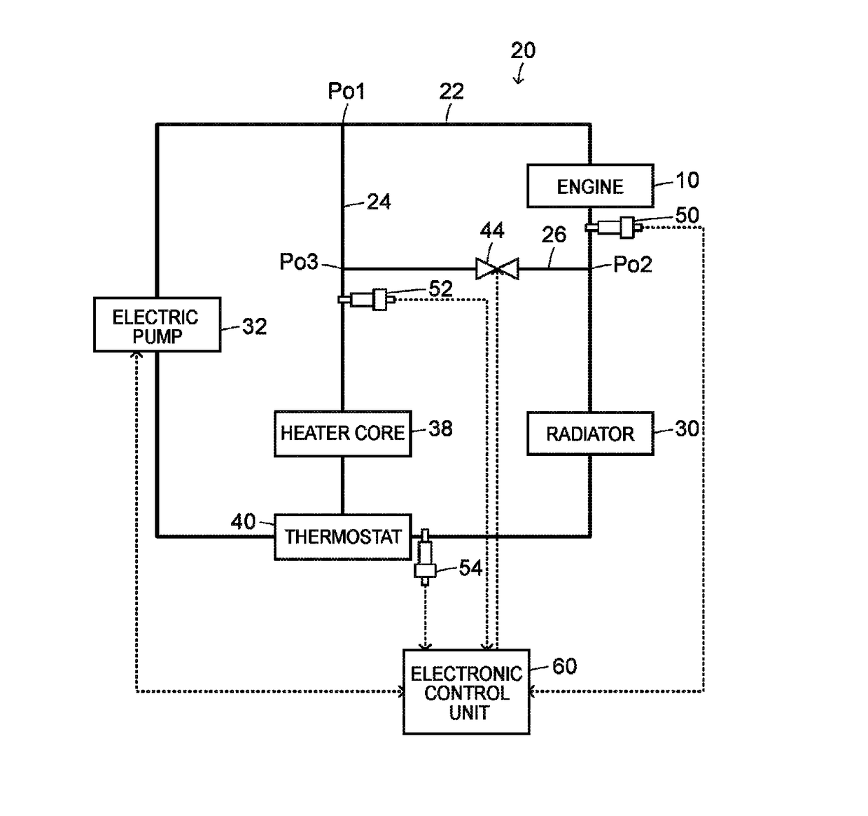
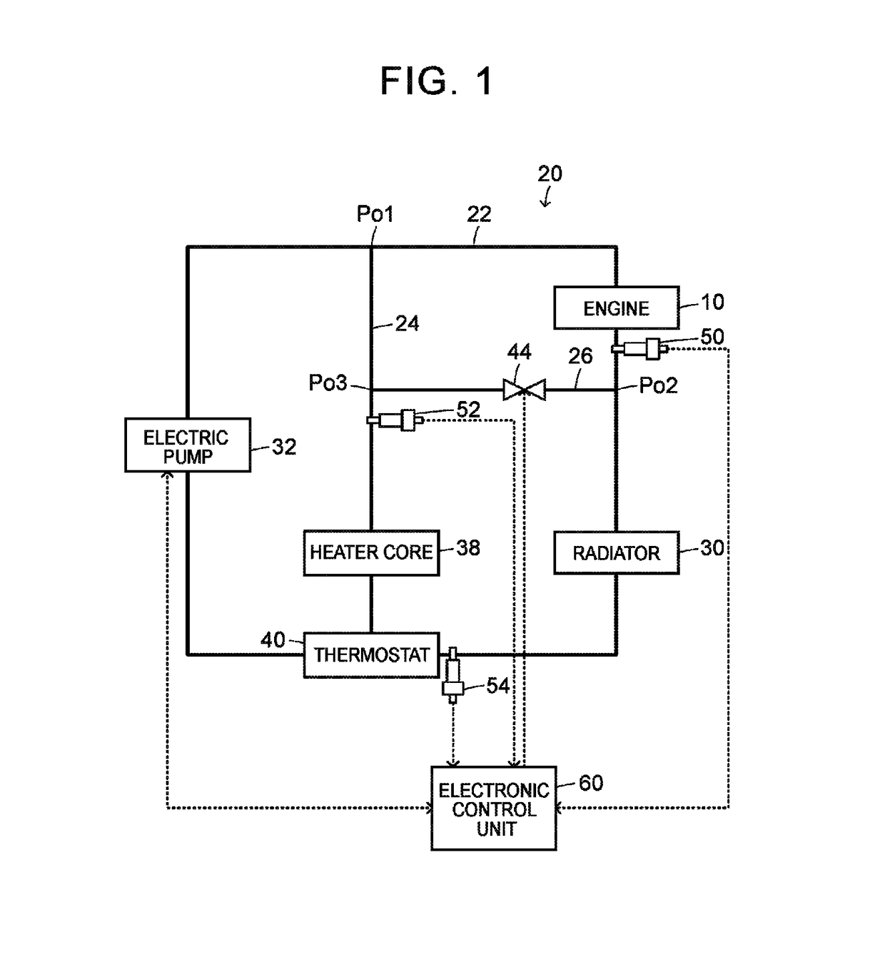
[0029]FIG. 1 is a configuration view that schematically shows the configuration of a cooling system 20 for an engine as an example of the embodiment of the present disclosure. The cooling system 20 for an engine according to the embodiment is mounted on an automobile that travels by using power from an engine 10. As shown in FIG. 1, the cooling system 20 includes a circulation flow passage 22 that serves as a first flow passage, a bypass flow passage 24 that serves as a second flow passage, a communication flow passage 26 that serves as a third flow passage, a radiator 30, an electric pump 32, a thermostat 40 that serves as a first valve, a selector valve 44 that serves as a second valve, and an electronic control unit 60.

[0030]The circulation flow passage 22 is a flow passage that flows coolant (long life coolant (LLC)) in order of the electric pump 32, the engine 10, the radiator 30, the thermostat 40 and the electric...


PUM


Abstract

A cooling system circulates a cooling medium between an engine and a radiator. The cooling system includes a determination unit. The determination unit sets a relatively small predetermined value for a threshold when a thermostat is closed, and sets a predetermined value larger than the predetermined value for the threshold when the thermostat is open. The determination unit determines that there is a stuck-closed failure in a selector valve when a temperature difference between a coolant temperature from a first coolant temperature sensor and a coolant temperature from a second coolant temperature sensor is larger than or equal to the threshold.

Description

CROSS-REFERENCE TO RELATED APPLICATIONS[0001]The present application claims priority to Japanese Patent Application No. 2015-066902 filed on Mar. 27, 2015, the entire contents of which, including the specification, drawings and abstract, are incorporated herein by reference in its entirety.BACKGROUND[0002]1. Technical Field[0003]The disclosure relates to a cooling system for an engine.[0004]2. Description of Related Art[0005]Generally, there is suggested a cooling system for an engine including a first coolant circuit, a second coolant circuit, a thermostat, a valve, a first coolant temperature sensor, a second coolant temperature sensor and an engine cooling control unit (see, for example, Japanese Patent No. 4883225). The cooling system determines whether there is a stuck-closed failure in the valve based on a temperature difference between a first coolant temperature that is detected by the first coolant temperature sensor and a second coolant temperature that is detected by the ...

Claims


Application Information

Patent Timeline
Patent Type & Authority Patents(United States)
IPC IPC(8): F01P11/16
CPCF01P11/16F01P2031/32F01P2025/32F01P2025/30
Inventor HOSOKAWA, YOHEI
Owner TOYOTA JIDOSHA KK
Why Eureka
Try Eureka