Failure determination device for shutter device of vehicle

a technology of failure determination and shutter device, which is applied in the direction of machines/engines, propulsion parts, process and machine control, etc., to achieve the effect of positive avoiding a determination error

Active Publication Date: 2014-12-02
HONDA MOTOR CO LTD
View PDF23 Cites 6 Cited by
  • Summary
  • Abstract
  • Description
  • Claims
  • Application Information

AI Technical Summary

Benefits of technology

[0007]The present invention has been made to provide a solution to such problems, and an object thereof is to provide a failure determination device for a shutter device of a vehicle, which can determine a failure of the shutter device with accuracy in a short time period.Solution to Problem
[0030]In a case where the operation conditions of the aircon are changed, for example, in a case where the temperature setting of the aircon is changed or inside air circulation / outside air introduction is switched, the refrigerant pressure varies accordingly. With the configuration of this embodiment, the failure determine of the shutter device is inhibited when the operation conditions of the aircon are different between when the closing command is output and when the opening command is output. This makes it possible to positively avoid a determination error caused by a change in the operation conditions of the aircon.

Problems solved by technology

Further, in this failure determination device, when the engine coolant temperature at the time when a predetermined time has elapsed after the command to the grille shutter is switched from a closing command to an opening command is not lower than a first predetermined temperature A0, the engine coolant temperature has not lowered, and hence it is determined that the grille shutter is stuck on the closed side.

Method used


Image

  • Failure determination device for shutter device of vehicle
  • Failure determination device for shutter device of vehicle
  • Failure determination device for shutter device of vehicle

Examples


first embodiment

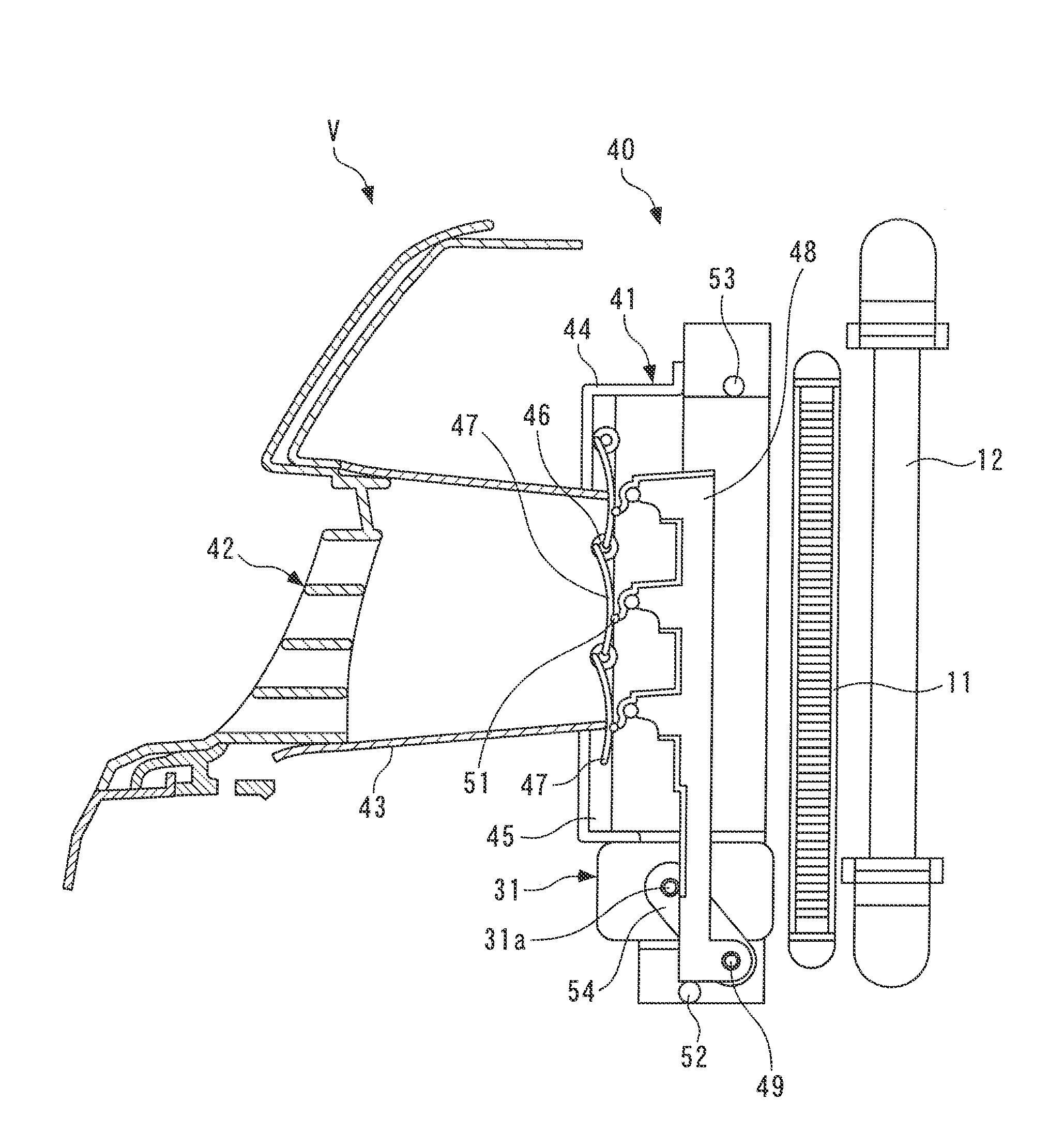
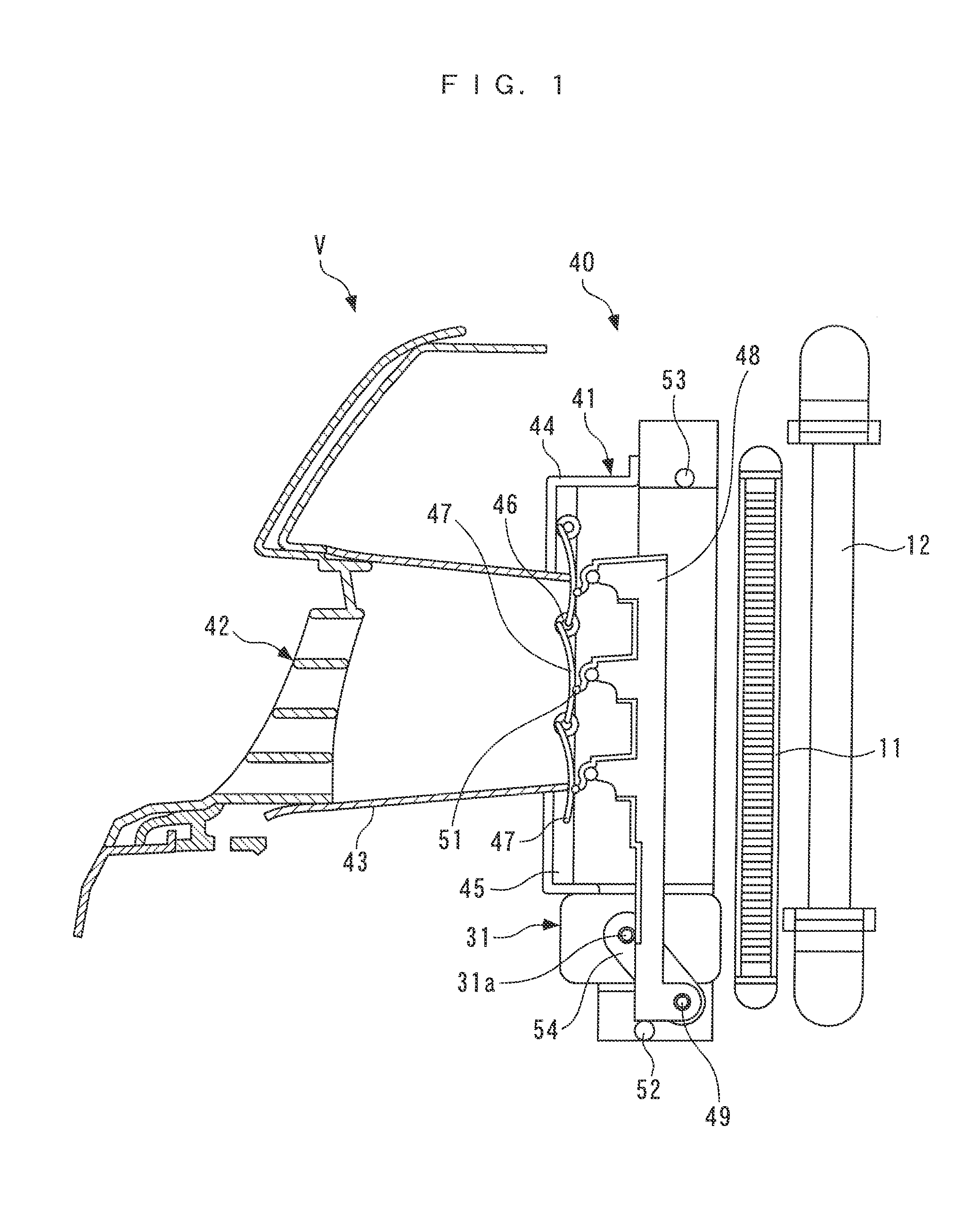
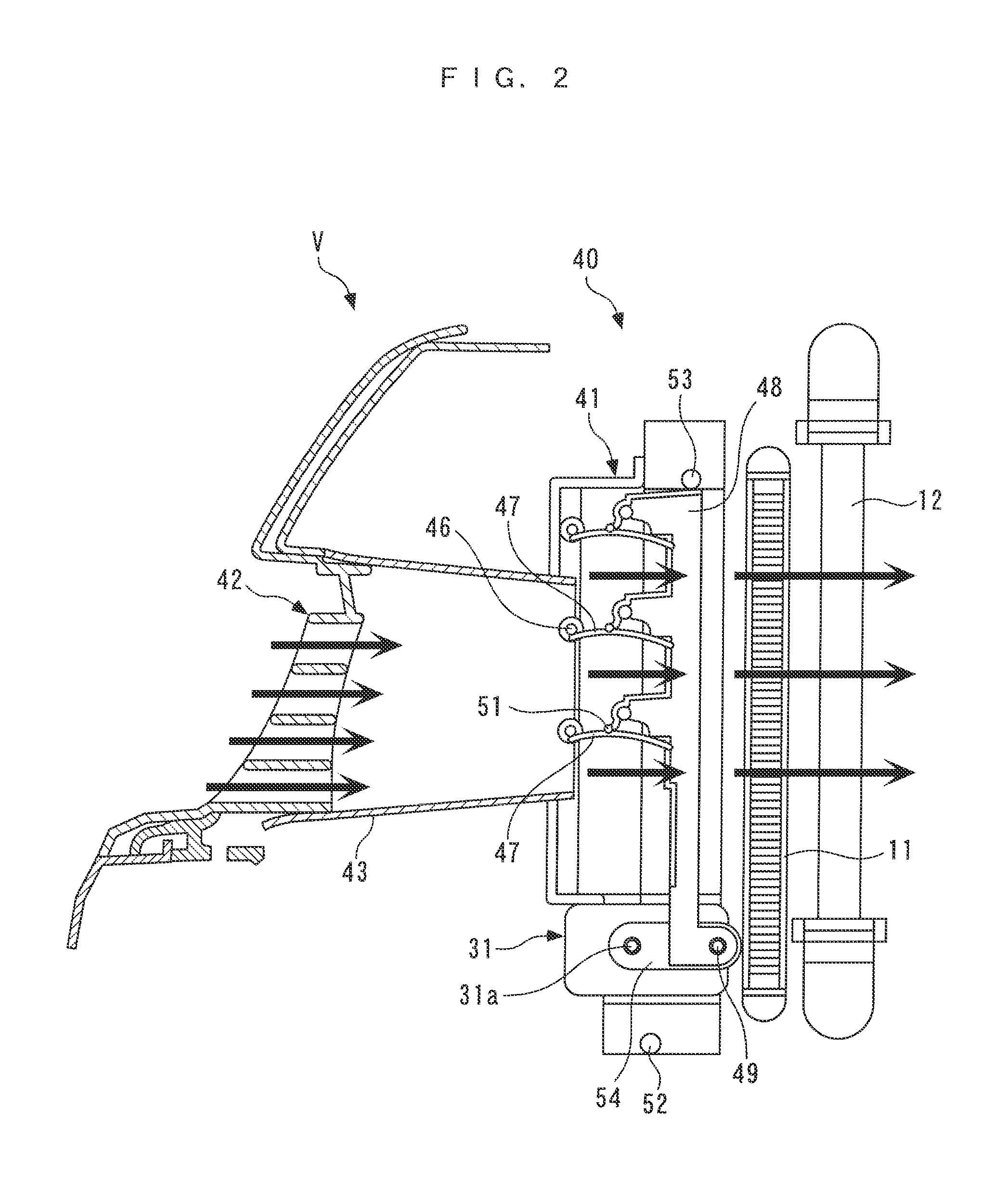
[0070]Next, a failure determination process for the grille shutter device 41 according to the present invention will be described with reference to FIGS. 4 to 20. The failure determination process determines a failure of the grille shutter device 41 according to the refrigerant pressure PD, and FIG. 4 corresponds to a main routine, while FIGS. 5 to 17 correspond to subroutines. Each process is executed whenever a predetermined time period dT elapses.

[0071]In the main routine of FIG. 4, first, in a step 1 (denoted as “S1” in FIG. 4; steps mentioned hereinafter are also denoted in the same manner), a detection condition determination process is executed. The detection condition determination process determines whether or not a state of the engine 3 and a state of the aircon 32 are suitable for detecting a failure of the grille shutter device 41, and FIG. 5 shows a subroutine therefor.

[0072]In the present process, first, in steps 21 to 32, it is determined whether or not the following ...

second embodiment

[0224]Further, although in the second embodiment, as the peak values of the refrigerant pressure PD during the post-switching process, for use in failure determination, the maximum closing command-time peak pressure PDPCMAX and the minimum opening command-time peak pressure PDPOMIN are used, they may be only required to be those calculated according to the closing command-time peak pressure PDPC β and the opening command-time peak pressure PDPOβ stored in the post-switching process, and may be the closing command-time peak pressure PDPCβ and the opening command-time peak pressure PDPOβ themselves.

[0225]Further, although the embodiments are examples of application of the present invention to the vehicle that mounts the gasoline engine, this is not limitative, but the present invention may be applied to any suitable vehicle that mounts one of various engines other than the gasoline engine, such as a diesel engine, and may be applied to a hybrid vehicle that uses an engine and an elect...


PUM


Abstract

A failure determination device capable of performing failure determination for a shutter device of a vehicle with accuracy in a short time period. In an engine room of a vehicle, a condenser for a refrigeration cycle for an aircon is provided and at a front grille of the vehicle, a grille shutter device is provided for introducing ambient air for cooling the condenser into the engine room by opening a grille shutter. According to the failure determination device of the shutter device, a pressure of the refrigerant discharged from the condenser is detected as a refrigerant pressure. A failure of the grille shutter device is determined based on the refrigerant pressure, which changes at a large rate according to the opening / closing of the grille shutter, enabling failure determination with accuracy in a short time period.

Description

TECHNICAL FIELD[0001]The present invention relates to a failure determination device for a shutter device of a vehicle that is openably and closably provided at a front opening of a vehicle, and determines a failure of a shutter device which introduces ambient air into an engine room.BACKGROUND ART[0002]As a conventional failure determination device for a shutter device of a vehicle of this kind, one described e.g. in PTL 1 is known. A radiator is disposed in an engine room of a vehicle, and in a front opening, a grille shutter is disposed for feeding ambient air for cooling the radiator. If a detected temperature of coolant in the engine (hereinafter referred to as “engine coolant temperature”) is not lower than a predetermined temperature, the grille shutter is opened, and if it is lower than the predetermined temperature, the grille shutter is closed. With this, the amount of ambient air introduced into the engine room is controlled according to the engine coolant temperature, wh...

Claims


Application Information

Patent Timeline
Patent Type & Authority Patents(United States)
IPC IPC(8): B60H1/32B60H1/00G06F17/00B60K11/08
CPCB60H1/00871B60H1/00978B60K11/085B60H2001/326G06F17/00Y02T10/88
Inventor SATO, DAISUKEMAKI, HIDETAKAOHNISHI, HIROYUKIENDO, MASATOSHIOSHIMA, YOSHIKAZU
Owner HONDA MOTOR CO LTD
Why Eureka
Try Eureka