
Output circuit and method for detecting whether load connected to connection port corresponding to output circuit

Active Publication Date: 2016-10-13
ALICORP
View PDF9 Cites 4 Cited by
  • Summary
  • Abstract
  • Description
  • Claims
  • Application Information

AI Technical Summary

Benefits of technology

The present invention provides a method to eliminate an offset in the output voltage of an electronic device. The offset is caused by the coupling capacitor between the output circuit and the load, which affects the accuracy of the output voltage measurement. The method involves introducing a level adjustment circuit into the output circuit to sample and adjust the voltages generated at the output terminal at different times. This allows the determination circuit to identify the connection status of the load regardless of the offset. The technical effect of the invention is to improve the accuracy of voltage measurements, ensuring the identification of the correct connection status.

Problems solved by technology

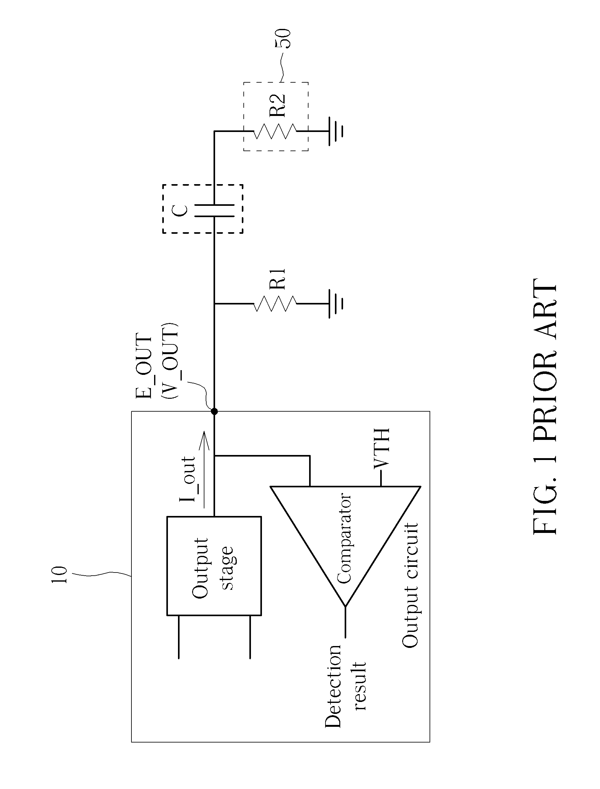
However, in actual use, not every connecting port is not connected to a display device, but output circuits or signal processing circuits corresponding to the “un-connected” connecting port still keeps operating since it is not informed of connection status (i.e., whether the display device is connected to the connecting port).
This leads to unnecessary power consumption.
However, such mechanically-driven switch and related signal generation circuit increases the implementation cost.
Therefore, the layout of the output circuit and the signal process circuit become more complicated, and what is even worse, the mechanically-driven switch may wear down or break down because of repeatedly uses.
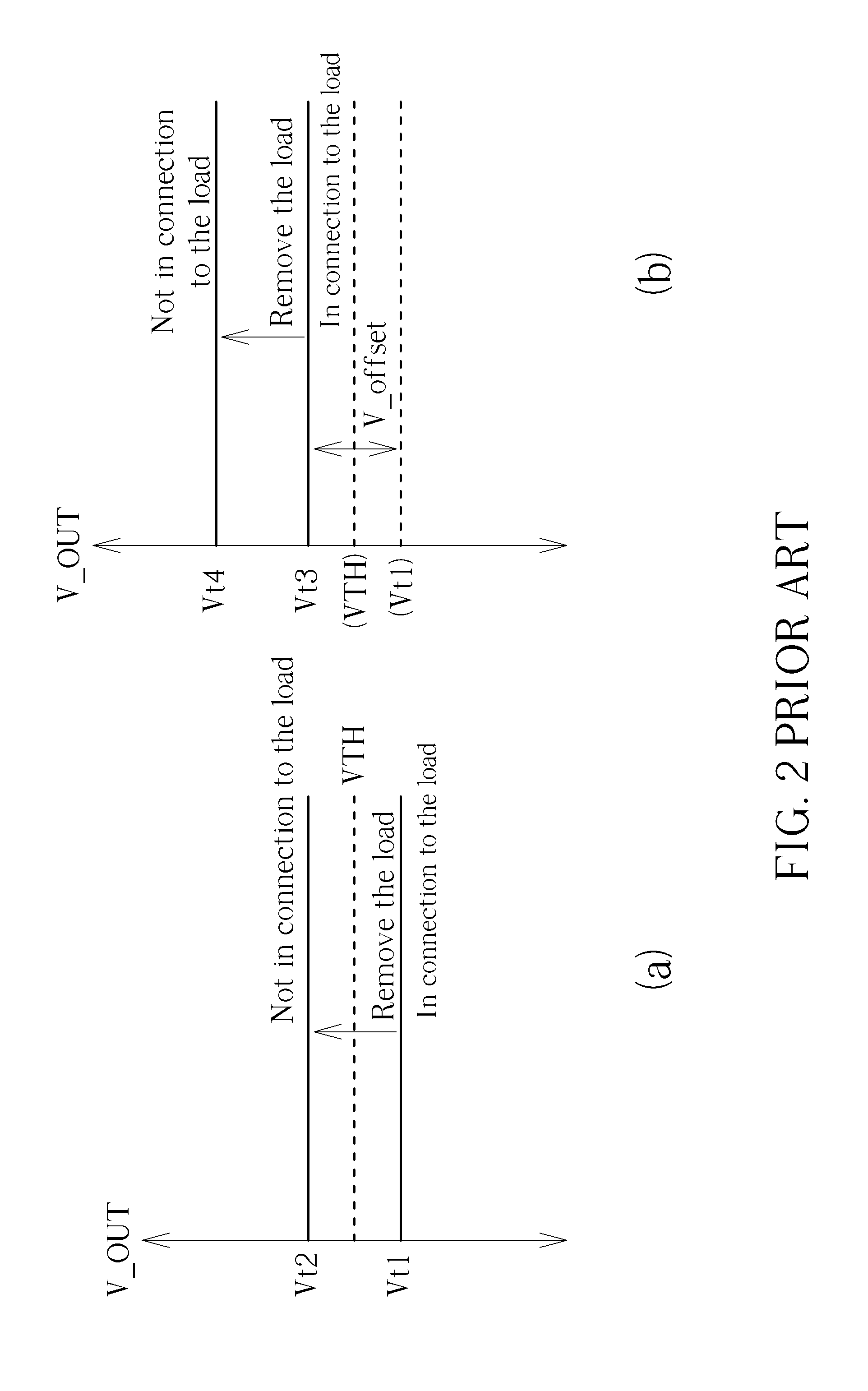
Unless the threshold voltage is designed to vary with the existence of the coupling capacitor C, this is impossible to determine a threshold voltage that is able to satisfy conditions of both AC coupling and DC coupling.
However, it is complicated to design a variable threshold voltage and may increase the complexity of the output circuit 10.

Method used


Image

  • Output circuit and method for detecting whether load connected to connection port corresponding to output circuit
  • Output circuit and method for detecting whether load connected to connection port corresponding to output circuit
  • Output circuit and method for detecting whether load connected to connection port corresponding to output circuit

Examples


Embodiment Construction

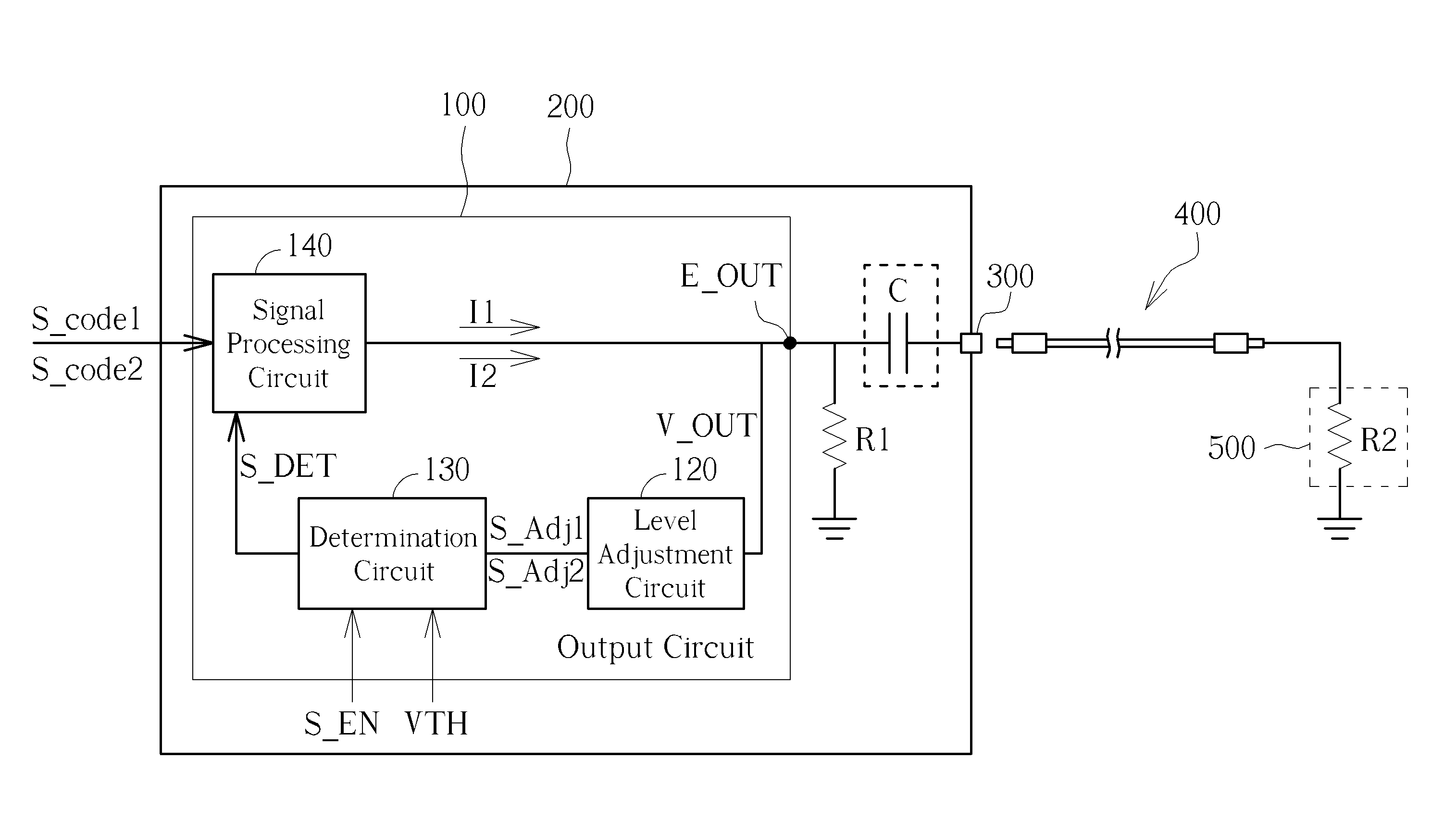
[0021]FIG. 3 illustrates a schematic diagram of an output circuit according to one embodiment of the present invention. As illustrated, an output circuit 100 comprises a level adjustment circuit 120 and a determination circuit 130. The output circuit 100 has an output terminal E_OUT, which is connected to a connecting port 300 via wires / traces on a circuit board 200. There is a matching resistor R1 disposed on the circuit board 200, which is connected between the connecting port 300 and the output terminal E_OUT. The matching resistor R1 is used to match the impedance of an equivalent resistor R2 of an external device 500 (e.g. a display device), where resistances of resistor R1 and R2 are respectively represented as R1 and R2. A coupling resistor C may exist between the connecting port 300 and the output terminal E_OUT. The external device 500 is connected to one end of a transmission cable 400, and the other end of the transmission cable 400 may be plugged into the connecting port...


PUM


Abstract

An output circuit includes a level adjustment circuit and a determination circuit. The output circuit is employed for generating an output to an output terminal of the output circuit, where the output terminal is coupled to a connecting port. The level adjustment circuit is coupled to the output terminal and is employed for generating at least one adjusted signal according to a first voltage signal at the output terminal in a first period and a second voltage signal at the output terminal in a second period. The determination circuit is coupled to the level adjustment circuit and is employed for generating a determination signal according to the at least one adjusted signal, wherein the determination signal indicates whether a load is connected to the connecting port.

Description

BACKGROUND OF THE INVENTION[0001]1. Field of the Invention[0002]The present invention relates generally to an output circuit, and more particularly, to an output circuit, a related detecting circuit, and a video output circuit that can detect whether a load is connected to a connecting port corresponding to the output circuit.[0003]2. Description of the Prior Art[0004]Typically, multimedia playback devices, such as set-up boxes, output video and audio signals to display devices through connecting ports and transmission cables. Since there are a variety of different video signaling standards used by the display devices, a multimedia playback device usually has several connecting ports complying with different video signaling standards, such as, composite video, S-Video, component video, digital visual interface (DVI) and high definition multimedia interface (HDMI) standards. However, in actual use, not every connecting port is not connected to a display device, but output circuits or...

Claims


Application Information

Patent Timeline
IPC IPC(8): H04N17/04G01R27/02
CPCG01R27/02H04N17/045G01R19/16557G01R19/16576
Inventor HSU, CHIH-YUANWANG, YU-SHIN
Owner ALICORP
Learn More