
Method and system for locating an acoustic source

a technology of acoustic source and acoustic sensor, which is applied in the direction of direction/deviation determination system, instruments, and wellbore/well accessories, etc., can solve the problem that the strength of an acoustic source is usually unknown, the strength of a signal as detected by an acoustic sensor is not a reliable indicator of the distance between the source and the source, etc. problem, to achieve the effect of improving accuracy

Active Publication Date: 2018-05-29
CHEVROU USA INC
View PDF22 Cites 17 Cited by
  • Summary
  • Abstract
  • Description
  • Claims
  • Application Information

AI Technical Summary

Benefits of technology

[0020]In one embodiment the processing that is performed comprises separating the received acoustic signals into their component frequencies and determining the location in dependence on at least one (or more) of the component frequencies and the known speed of sound for that frequency through the surrounding medium. This provides advantages that it then becomes possible to account for local dispersion characteristics in the area being monitored, without requiring extensive and laborious calibration of the system upon installation. Instead, a frequency is used the speed of sound for which is known from a priori dispersion measurements.
[0021]Within the above embodiment the processing further comprises evaluating a plurality of cost functions that relate acoustic sensor position to source position in dependence on the respective time delays experienced by component frequencies of the received acoustic signal; and determining a cost function indicative of the distance to the source position. Hence, it becomes possible to determine distance to the source taking into account local dispersion conditions across a number of frequencies, which should improve accuracy.

Problems solved by technology

A limitation of this prior art is that the number of sensors that may be deployed is limited at typically less than one hundred, and their spatial locations are either constant or may only be changed by laborious and time-consuming re-deployment of the sensor array.
However, the strength of an acoustic source is usually unknown and so the strength of a signal as detected by an acoustic sensor is not a reliable indicator of the distance between the source and the sensor and therefore of position.

Method used


Image

  • Method and system for locating an acoustic source
  • Method and system for locating an acoustic source
  • Method and system for locating an acoustic source

Examples


Embodiment Construction

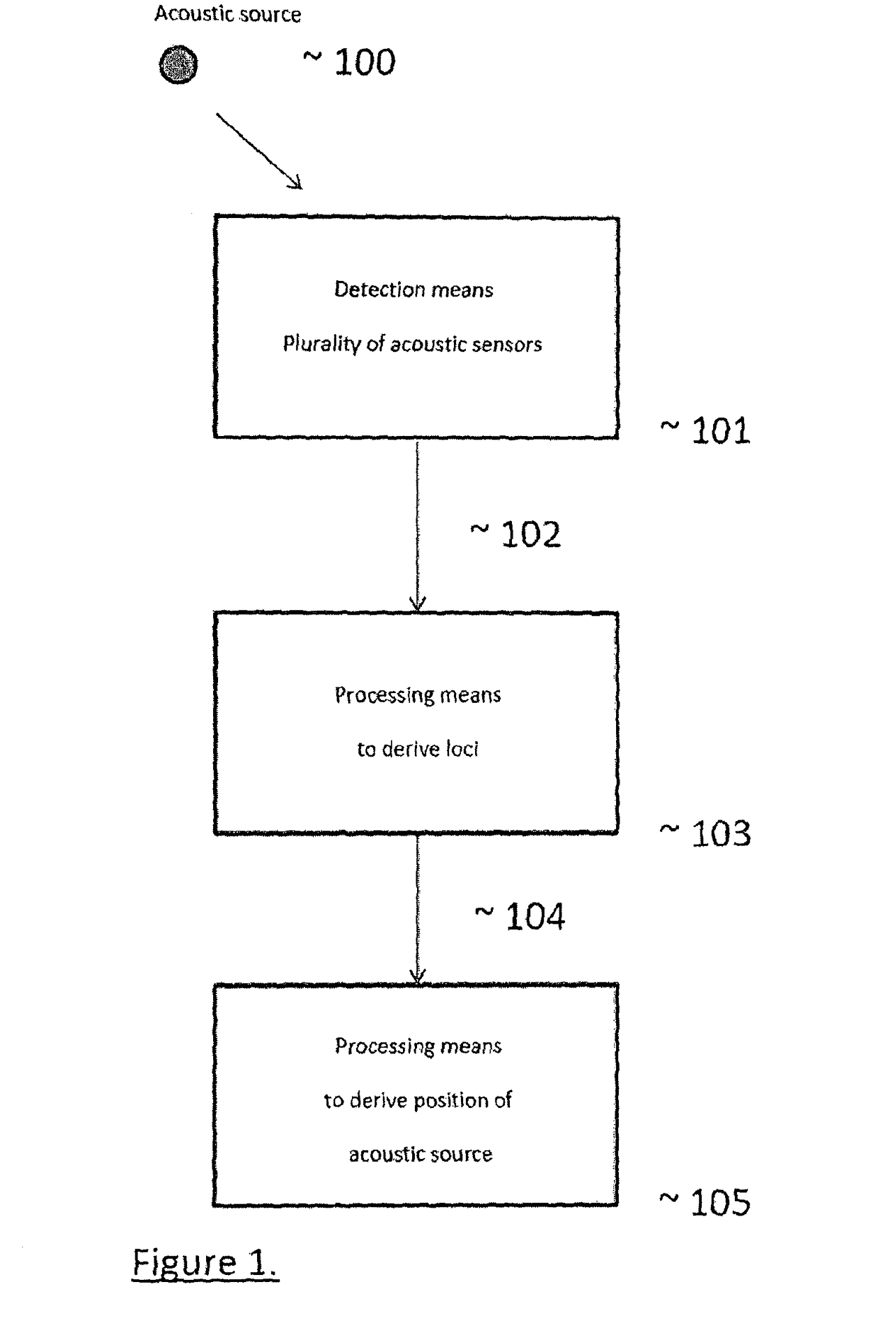
[0065]With reference to FIG. 1, the present invention consists of one or more detection means each consisting of a plurality of acoustic sensors (101) from which one or a plurality of signals (102) as a function of space and time may be obtained which results from acoustic energy from one or a plurality of optical sources (100) falling on the detection means (101), a processing means (103) which derives one or a plurality of loci (104) from the signal (102), and a processing means (105) which derives a position for one or a plurality of acoustic sources (100) from the one or plurality of loci (104). In preferred embodiments of the invention, the plurality of acoustic sensors is high and they are closely placed, preferably implemented with a distributed acoustic sensor, and more preferably, a distributed optical fibre acoustic sensor, and still more preferably, where both the acoustic amplitude and phase are provided. An example of such preferred detection means is described in paten...


PUM


Abstract

A method and a system are provided, in which acoustic signals received by distributed acoustic sensors are processed in order to determine the position of a source or sources of the acoustic signals. The method and system are able to determine the position of several acoustic sources simultaneously, by measuring the corresponding several acoustic signals. Furthermore, the strength of the acoustic signal or signals can be determined. The location of the acoustic source may be overlaid on a map of an area being monitored, or be used to generate an alarm if perceived to correspond to a threat or an intrusion, for example in a pipeline monitoring application. Alternatively, the method and systems can be used to monitor a hydraulic fracturing process.

Description

CROSS-REFERENCE TO RELATED APPLICATIONS[0001]This application is a National Stage application of International Patent Application No. PCT / GB2012 / 000490, filed on Jun. 6, 2012, which claims priority to British Patent Application No. 1109372.1, filed on Jun. 6, 2011, and British Patent Application No. 1113381.6, filed on Aug. 3, 2011. These priority applications are hereby incorporated by reference in their entireties.TECHNICAL FIELD[0002]The present invention relates to the field of locating acoustic sources and provides a method and a system for locating acoustic sources in which a plurality of acoustic sensors are distributed in space and acoustic signals received at the plurality of acoustic sensors are processed in order to determine the position of the acoustic source. In a particular embodiment, the plurality of acoustic sensors is provided in a distributed optical fibre sensor.BACKGROUND TO THE INVENTION[0003]There are many applications in which it is desirable to determine, w...

Claims


Application Information

Patent Timeline
Patent Type & Authority Patents(United States)
IPC IPC(8): G01S5/20G01V1/18G01H9/00
CPCG01S5/20G01V1/186G01H9/004E21B43/119E21B43/26G01D5/353G01D5/35383G01S3/801G01S3/808G01S3/8083G01S5/22G01V8/24G08B13/186E21B47/095E21B47/107
Inventor FARHADIROUSHAN, MAHMOUDPARKER, TOMYOUSIF, KAMIL
Owner CHEVROU USA INC
Learn More