
Software system for dynamic feature extraction for structural health monitoring

Active Publication Date: 2018-05-29
BENTLEY SYST INC
View PDF4 Cites 7 Cited by
  • Summary
  • Abstract
  • Description
  • Claims
  • Application Information

AI Technical Summary

Benefits of technology

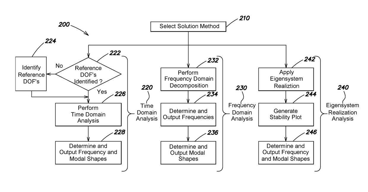
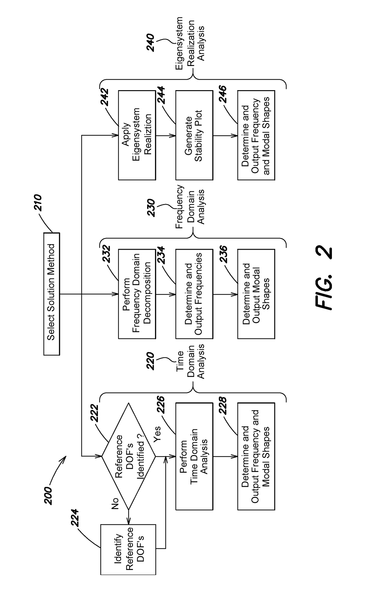
The patent describes a software system that can extract dynamic features from data collected by sensors on a structure. The system uses time-domain analysis, frequency domain decomposition, or an eigensystem realization algorithm to analyze the data. The system guides the user in selecting the most effective parameters for the chosen analysis method and automatically performs the analysis on the data. The system can handle data related to ambient vibrations or earthquake-induced vibrations. The technical effect of this patent is to provide a tool for extracting dynamic features from data collected by sensors on a structure, which can aid in the analysis and monitoring of structures in real-time.

Problems solved by technology

Structural deterioration is inevitable for structures (e.g., bridges, dams, buildings, etc.) that are subjected to adverse operational and environmental conditions over long service lives.
If existing deficiencies are not improved, for example, damage and cracks detected and repaired at an early stage, minor deficiencies may grow and lead to expensive repairs or, if unaddressed for too long, to catastrophic failures.
The visual inspections are often quite time-consuming and labor-intensive, and even if diligently performed, may miss many types of hidden deterioration.
Accordingly, they provide an inadequate and unreliable solution to the problem of detecting structural deterioration.
However, extracting dynamic features from data sets of a SHM system often proves challenging for engineers in the field.
While certain specific approaches have been developed for particular use cases, there is a lack of a generic approach that can be implemented in a user-friendly software system for extracting dynamic features.

Method used


Image

  • Software system for dynamic feature extraction for structural health monitoring
  • Software system for dynamic feature extraction for structural health monitoring
  • Software system for dynamic feature extraction for structural health monitoring

Examples


Embodiment Construction

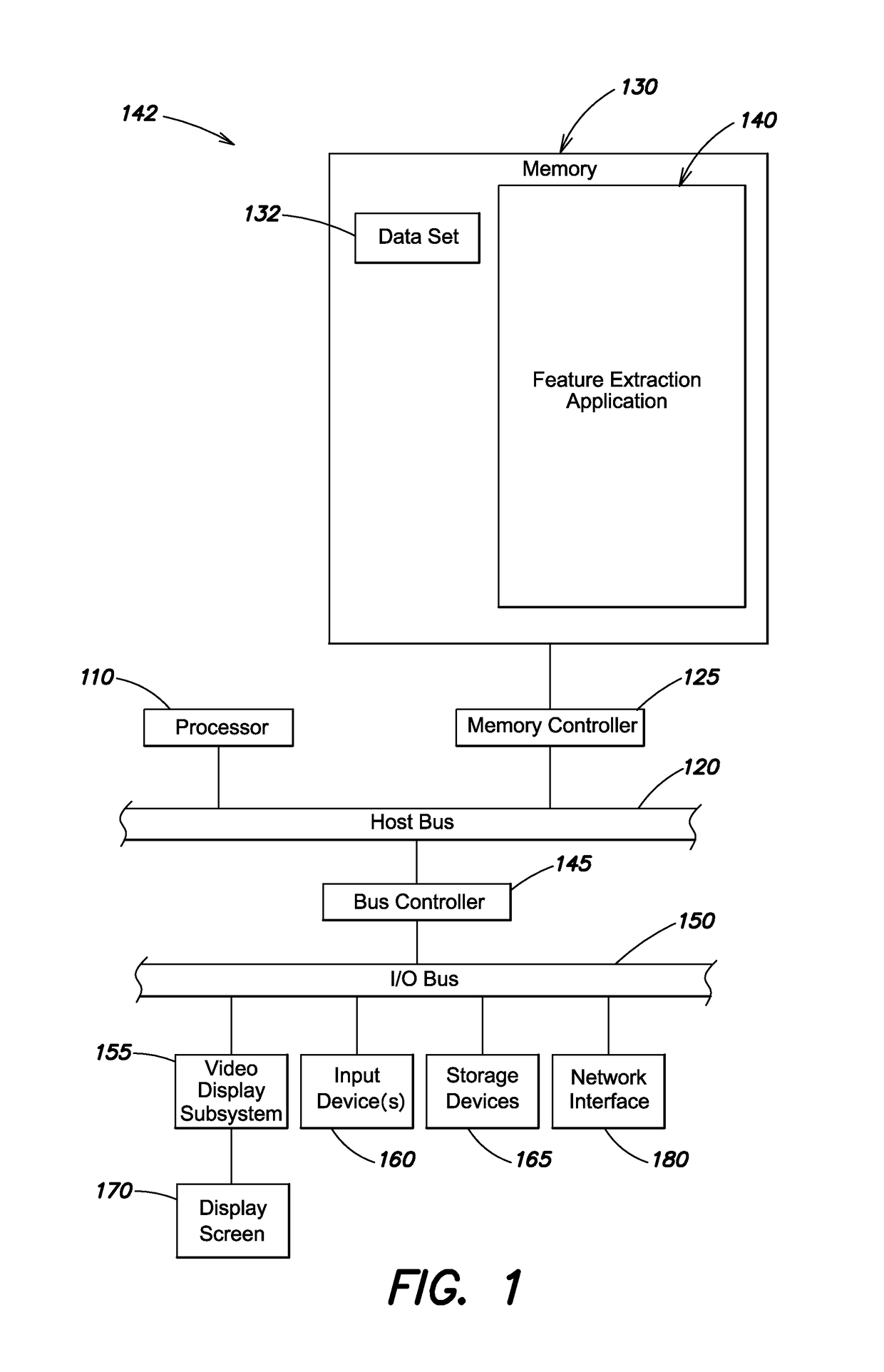
[0019]FIG. 1 is a block diagram of an example electronic device 100 (e.g., a computer) that may be used with the present techniques. The electronic device 100 includes at least one processor 110 coupled to a host bus 120. The processor 110 may be any of a variety of commercially available processors, such as an Intel x86 processor, or another type of processor. A volatile memory 130, such as a Random Access Memory (RAM) is also coupled to the host bus via a memory controller 125. When in operation, the memory 130 stores software (i.e. processor-executable instructions) and data that are provided to the processor 110. An input / output (I / O) bus 150 is coupled to the host bust 120 via a bus controller 145. A variety of additional components are coupled to the I / O bus 150. For example, a video display subsystem 155 is coupled to the I / O bus 150. The video display subsystem may include a display screen 170 and hardware to drive the display screen. At least one input device 160, such as a...


PUM


Abstract

In an example embodiment, a dynamic feature extraction tool receives a data set from a SHM system that includes a plurality of sensors affixed to a structure (e.g., a bridge, dam, building, etc.), the data set including at least one of ambient vibration data or earthquake vibration data. A solution method is selected from among, for example, time domain analysis, frequency domain decomposition or eigensystem realization analysis. The dynamic feature extraction tool guides a user to select at least one parameter value used in the selected solution method from a subset of determined-effective parameter values computed by the software tool. The dynamic feature extraction tool then automatically performs the selected solution method on the data set using the selected at least one parameter value to determine dynamic features (e.g., frequencies or modal shapes), and displays a graphical representation of the dynamic features in a UI.

Description

BACKGROUNDTechnical Field[0001]The present disclosure relates generally to structural health monitoring, and more specifically to techniques for extracting dynamic features from data sets of a structural health monitoring (SHM) system.Background Information[0002]Structural deterioration is inevitable for structures (e.g., bridges, dams, buildings, etc.) that are subjected to adverse operational and environmental conditions over long service lives. For example, in the year 2006, over 26% of the 600,905 bridges in the U.S. were rated as either structurally deficient or functionally obsolete. As a result of economic considerations, most of these aging structures are still in service. If existing deficiencies are not improved, for example, damage and cracks detected and repaired at an early stage, minor deficiencies may grow and lead to expensive repairs or, if unaddressed for too long, to catastrophic failures.[0003]To try to address these issues, many structures are periodically inspe...

Claims


Application Information

Patent Timeline
IPC IPC(8): G06F3/048G01M99/00G06F3/0484G06F3/0482
CPCG06F3/04847G06F3/0482G01M99/00G01H3/04G01M5/0008G01M5/0066
Inventor WU, ZHENG YIZHAO, JIELI, JINGCHENGZHANG, JINGYUAN
Owner BENTLEY SYST INC
Learn More