Plate for osteosynthesis device and method of preassembling such device

Inactive Publication Date: 2018-06-05
LDR MEDICAL
View PDF4 Cites 0 Cited by
  • Summary
  • Abstract
  • Description
  • Claims
  • Application Information

AI Technical Summary

Benefits of technology

The invention is an osteosynthesis device for spine surgery that includes a plurality of implants that can be screwed into vertebrae and joined with a plate or bar to hold or displace the spine. The plate can be fixed without preventing the implant from rotating or moving in a certain clearance range. The implant has a mobile part called the clamping support that can be rotated after the plate is assembled on the implant. The clamping support has a concave part that fits tightly with a circular part of the support head to prevent rotation. The implant also has a longitudinal bore and an opening for bone fusion. These features improve the stability and flexibility of the device during spine surgery.

Problems solved by technology

However, such a device requires that the clamping nut only be fitted on the screw after the screws and the plate have been positioned.
Therefore, said nut can only be inserted onto the screw head during the operation, with all the difficulties and risks of loss that may be caused by handling and assembling a small part inside a human body.
This operation is all the more problematic when said operation is conducted by means of endoscopy, for example when it is necessary to implant via the anterior approach, i.e. via the front of the body or on the front face of the spine.
Therefore, in the event of delicate operative conditions, it is difficult to successfully position the plate very close to the spine.
This problem arises for example when the shape of the spine comprises too many irregularities, due to spinal displacement or deformation or in the presence of outgrowths such as osteophytes.
There are similar problems in the case of implantation by the anterior approach, i.e. via the front of the body or on the front face of the spine.
Indeed, the anatomical conditions in this case frequently only leave space for a compact size.
In addition, it is often necessary to work by means of endoscopy in this case, which renders the operation difficult and gives a less satisfactory view of the implant insertion depth.
However, during positioning or subsequently, such a screw may form anchoring which is not sufficiently strong and is liable to be dislodged or torn from the vertebra wherein it is implanted.

Method used


Image

  • Plate for osteosynthesis device and method of preassembling such device
  • Plate for osteosynthesis device and method of preassembling such device
  • Plate for osteosynthesis device and method of preassembling such device

Examples


Embodiment Construction

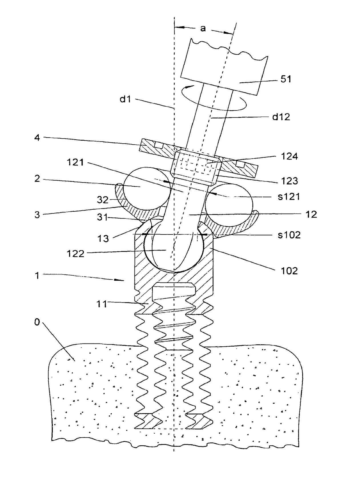
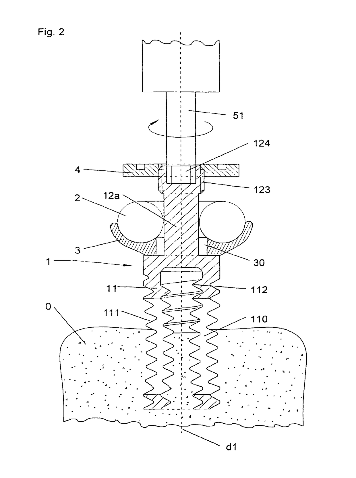
[0049]In an embodiment represented in FIG. 2, the device according to the invention comprises an implant 1 comprising a first end 11 equipped with an outer threading 111, and is illustrated after a first having been screwed in the bone substance of a vertebra 0, after insertion of a plate 2 and during the final approach. Said first end 11 also comprises a cavity or an inner bore, itself equipped with an inner threading 112 wherein the screwing direction is the same as that of the outer threading 111. During the screwing of the implant into the vertebra 0, part of the bone substance tends to fill said cavity and is assisted therein by the action of the inner threading. Preferentially, the inner threading 112 and the outer threading 111 are of the same pitch, so as to minimize the strain exerted on the bone substance at the entry of the bore during screwing.

[0050]The wall between the inner cavity and the outside of the implant has one or more openings, referred to as bone fusion holes...


PUM

PropertyMeasurementUnit
Angleaaaaaaaaaa

Abstract

Various methods, devices, and systems are disclosed that facilitate easier and more compact implantation of osteosynthesis devices. In some embodiments, implants are screwed into two vertebrae and a plate is used to hold and displace the spine. In some plate embodiments, at least one longitudinally elongated opening is disposed at one end of the plate and partially opening onto an edge of the plate. In some plate embodiments, at least one longitudinally elongated opening is disposed at one end of the plate having a portion sufficiently large to be inserted without disassembly in the fixation means of an implant already screwed into the spine when the fixation means are already assembled.

Description

CROSS-REFERENCE TO RELATED APPLICATIONS[0001]This application is a continuation of U.S. patent application Ser. No. 14 / 584,674 filed Dec. 29, 2014, and issuing as U.S. Pat. No. 9,549,766 on Jan. 24, 2017, which is a continuation of U.S. patent application Ser. No. 13 / 454,927 filed Apr. 24, 2012, and issuing as U.S. Pat. No. 8,920,474 on Dec. 30, 2014, which is a continuation of U.S. patent application Ser. No. 10 / 492,827 filed Oct. 18, 2002, as International Application No. PCT / IB02 / 04307 and entering the National Stage in the United States with a 371(c) date of Jul. 15, 2004, and issuing Apr. 24, 2012, as U.S. Pat. No. 8,162,988. This application claims priority under 35 U.S.C. 119 to French Patent Application No. 01 13460, filed in FRANCE on Oct. 18, 2001, through U.S. patent application Ser. No. 10 / 492,827; U.S. patent application Ser. No. 13 / 454,927; and U.S. patent application Ser. No. 14 / 584,674.BACKGROUND[0002]The present invention relates to an osteosynthesis device, particu...

Claims


Application Information

Patent Timeline
IPC IPC(8): A61B17/70A61B17/86
CPCA61B17/7007A61B17/701A61B17/7041A61B17/7037A61B17/7011A61B17/7082A61B17/7001A61B17/864Y10T29/49826
Inventor DELECRIN, JOELALLAIN, JEROMETROPIANO, PATRICKGANGLOF, SERGEPONCER, REMI
Owner LDR MEDICAL
Why Eureka
Try Eureka